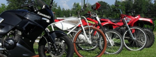
In my recent post Twin Leading Shoe Drum Brakes, I went over the basics of servicing a set of front brakes from an 81 Honda CM400E, & while I feel that it was a decent article from a how to standpoint, it was pointed out to me that someone who was completely new to the world of vintage motorcycle or do it yourself mechanics might not fully understand that I was trying to convey so I thought that it would be a good idea to go over the basics of the different type of vintage motorcycle drum brakes. For the purpose of this we will examine internal expanding shoe brakes, there are some ancient motorcycles & some minibikes that use a completely different drum brake style with an external brake band around the outside of the drum and I’m not going into that here unless you give me evidence of overwhelming popular need for explanations of external band brakes. Below you will find a few illustrations along with some brief explanations of mechanically actuated single leading shoe & twin leading shoe vintage motorcycle brakes. Just for grins I’ll show you an exploded illustration of a four leading shoe drum brake at the end of this post.
First let’s examine the single leading shoe drum brake. This is the type that you are most likely to encounter on motorcycles and atvs that utilize drum brakes at one end or the other. In fact there are still some lower end bikes that still use this system today. It is simple & it works.
When the brake arm is moved the brake cam pivots pressing the shoes into the drum generating friction to stop the wheel from turning. You may have noticed that I have the shoes marked leading and trailing and here is why. with the drum rotating in a clockwise direction the bottom shoe is pushed away from the brake cam by the rotating drum thus forcing it against the brake pivot post and the drum with greater force. The front or leading edge of the brake shoe is the first part of the shoe that the rotating drum passes over as it turns whereas the trailing edge is the last edge of the friction pad in the path of drum rotation. The top shoe in this illustration is labeled the trailing shoe because the trailing edge of the shoe is forced up into the drum first. Because it is not being pushed into a fixed pivot point by the rotation of the drum, the force generated tends to push it back towards the brake cam instead of pushing it more tightly into the drum. This means that the trailing shoe generates less stopping force than the leading shoe. There are a few advantages to this design with simplicity & reliability being at the top of the list. Another huge advantage to this design is that when you reverse the direction of wheel rotation, the trailing shoe becomes the leading shoe & the leading shoe becomes the trailing shoe. Why is this an advantage you may ask? Simple you get equal braking force whether you are going forward or reverse. While this is not that big a deal on a motorcycle it’s very important on vehicles such as atvs, tractors etc. that have reverse gears and travel backwards under power.
Up next let me throw up an illustration that I created of a simple twin leading shoe brake.
You will notice that there are still two brake shoes inside the drum but now there are two brake cams, two pivot posts, & two brake actuating arms joined together with a linkage. When the brake arms are moved it raising the leading edge of both shoes into the brake drum. Remember the advantages that the leading brake shoe has in stopping force that I told you about earlier? Now both brakes shoes are leading shoes giving you the maximum amount of friction possible from a drum brake design. This is the advantage to this design, increased stopping power. The disadvantages are that it is slightly more complicated and that it requires careful adjustment of the brake arm linkage to ensure that both shoes contact the drum at the same time. If the shoes do not open at an equal rate then only one of them will touch the drum under use giving you even less stopping power than a single leading shoe brake system. Also if you reverse the rotation of the wheel the twin leading shoes become twin trailing shoes, giving a reduced stopping power in reverse. On a motorcycle this doesn’t really matter though.
In the blog post about twin leading shoe drum brake I stated that they were the ultimate development in vintage motorcycle drum brakes, well that is almost true. There is a system that is capable of generating even more stopping force than that, the four leading shoe drum brake that was used in some exotic racing machinery. I shall not go into a huge amount of detail here except to say it is basically a pair of twin leading shoe systems mounted back to back on a common hub. I cribbed the image below from TheVincent.com.
If you are fortunate enough to own such a fine machine as an antique, Vincent, Brough, or MV Augusta racebike that uses 4 leading shoe brakes and you (or your staff mechanic) are not able to get it sorted properly, then load it into the enclosed trailer that you keep attached to your Land Rover, or Cayenne and have your butler deliver it to me along with a sackful of large unmarked bills and I will be glad to set it up for you, including a small amount of testing at a local track to make sure they are operating correctly.
Hi there,
My name is Floyd Finch III and I am the owner of this little motorcycle blog. Motorcycling has been one of two passions that I have consistently kept in my life since my childhood.
I believe every biker should have a little bit of outlaw in them.
At sometime early this morning in the hours just after midnight on March 23rd 2015 this little blog of mine passed the 100,000 all-time page view mark. While this may not seem all that significant compared to some of the mega-bloggers out there it makes me very happy. Hearing from readers in the comment sections or by email is a joy as well and hopefully I have helped a couple of people out.
Since founding this blog in February of 2011, my goal has been to help as many of my fellow motorcycling do it yourselfer home mechanics as I can, and to share the experiences that I have with those not fortunate enough to get out & do even the few shows & events that I take in.
Of course let’s not forget the occasional product reviews as well, I really am honest in my opinions of the products reviewed here whether for good or bad. This will continue to be my policy in the years to come.
This little motorcycle blog is beginning to exceed anything I dreamed of when I first started it. Although it was started as a hobby a good informative blog does incur some serious expenses so you may notice a few ads around the site. You know you’re going to shop online sooner or later and if you click on an ad here to start it would be a great boost for the blog without costing you a dime that you weren’t going to spend already!
Every year since 2011 the readership of this blog has shown serious solid growth, starting in 2011 I had 1982 page views, 2012 brought in 12,173 views, a huge jump in 2013 pushed readership up to 31,706 for the year, in 2014 there were 43,227 page views on this blog. My goal for this year is to push that number up to over 50,000 for the year with more to come in the years afterward.
So this is my most sincere & hearty thanks to all of the readers, and to those of you who have made products available for review. At this time I would like to encourage everyone who would like to keep up with all that is happening around here and to always have notification of my latest tutorials, tips & reviews please scroll down and sign up for my email list at the very bottom of the page below.
If you have a question that you would like to ask me directly or a product that you would like to have reviewed or if you are interested in advertising on this site please shoot me a line to: motopsyco@motopsyco.com
Thank you,
Floyd Finch III aka Motopsyco
Since I first posted this a couple of days ago it was pointed out to me that this article was not quite as beginner friendly as my normal do it yourself articles about explaining WHY you do some things. So if you don’t know the difference between a single leading shoe brake & a twin leading shoe brake or even how to identify which one you have or just to learn how they work please go to More About Vintage Motorcycle Drum Brakes and then come back to this page.
Twin leading shoe drum brakes are the ultimate development of motorcycle drum brakes. By using two lever arms and two cams to raise the leading edge of the brake shoes into the rotating drum they were able to generate a greater stopping force than a standard drum brake which pushes the leading edge of one brake shoe & the trailing edge of the other shoe into the drum. It was discovered early on that the shoe with the leading edge being forced into the drum generated much more friction than the trailing shoe. So until the development of powerful reliable disc brakes in the 1970s the twin leading shoe motorcycle brakes were pretty much the ultimate performance set up. Even after their performance was eclipsed by hydraulic disc brakes they were still considered adequate for small & medium sized machines right up into the early 1980s. Today there are still a few low end bikes fitted with drum brakes on the rear, but they are of the standard type, as even the low buck machines rely on powerful front discs for most of their stopping power. As far as I know today twin leading shoe motorcycle brakes are only found on antique, vintage, and custom bikes.
As always don’t forget that you can enlarge any picture on this blog by clicking on it.
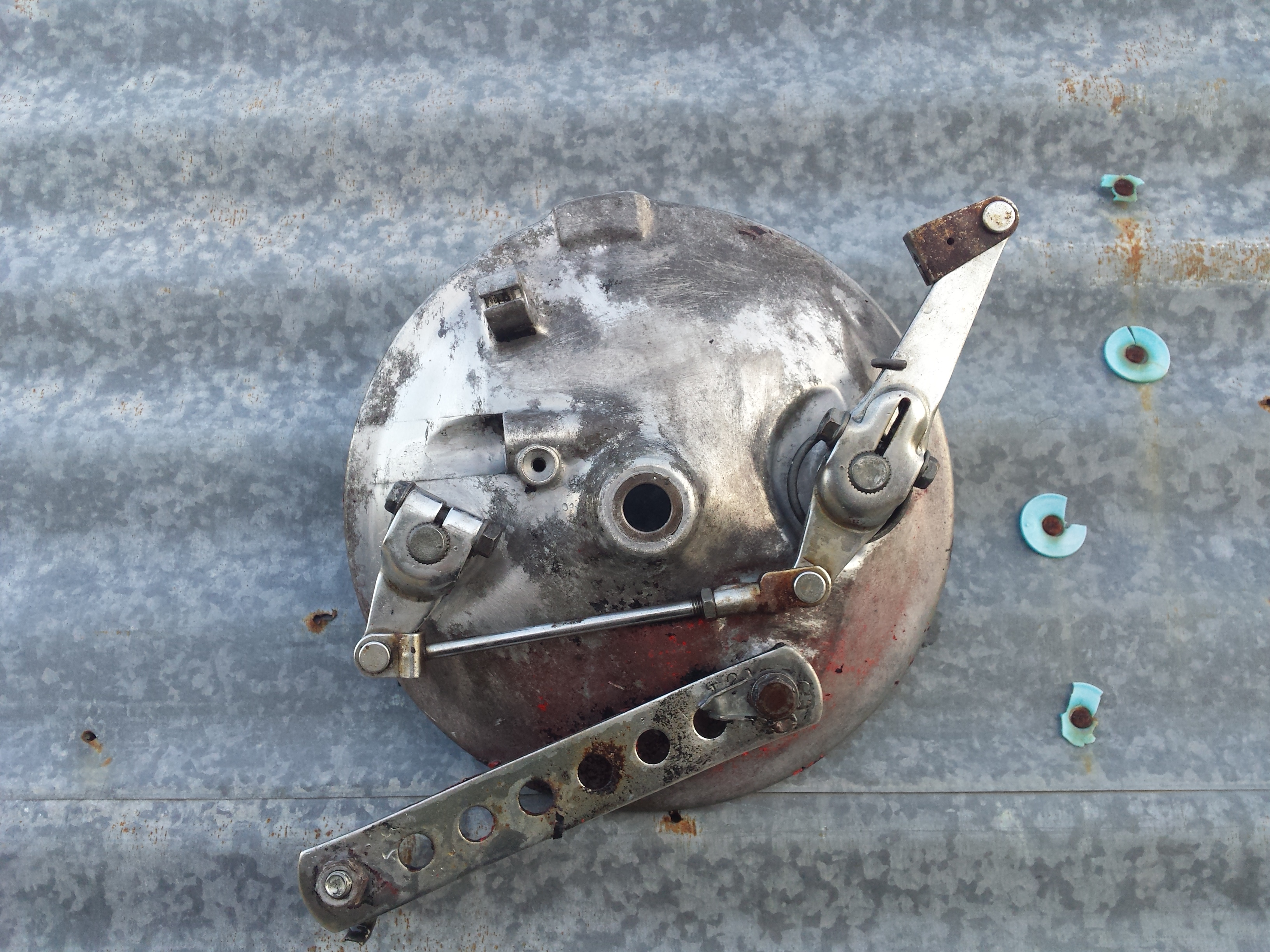
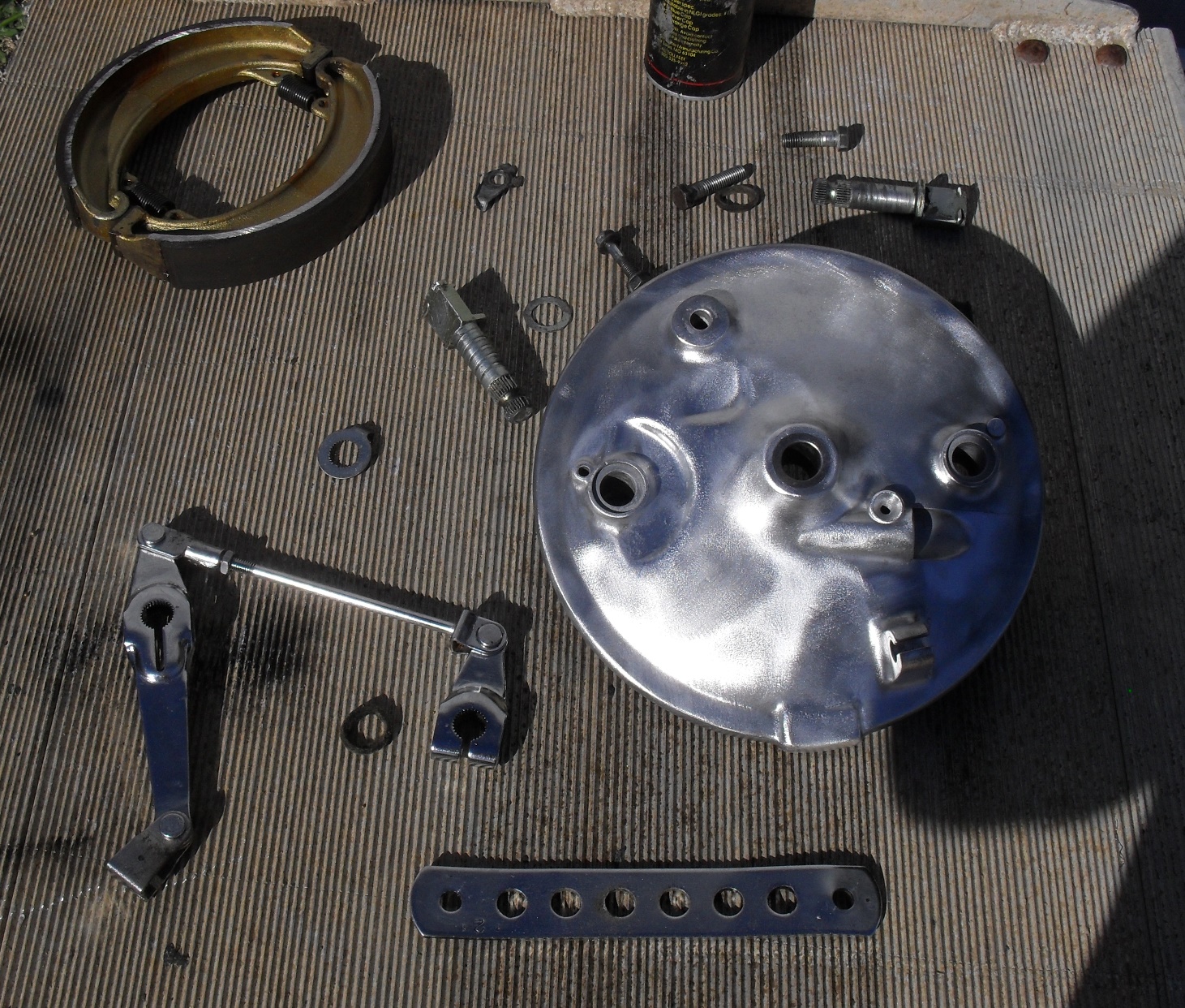
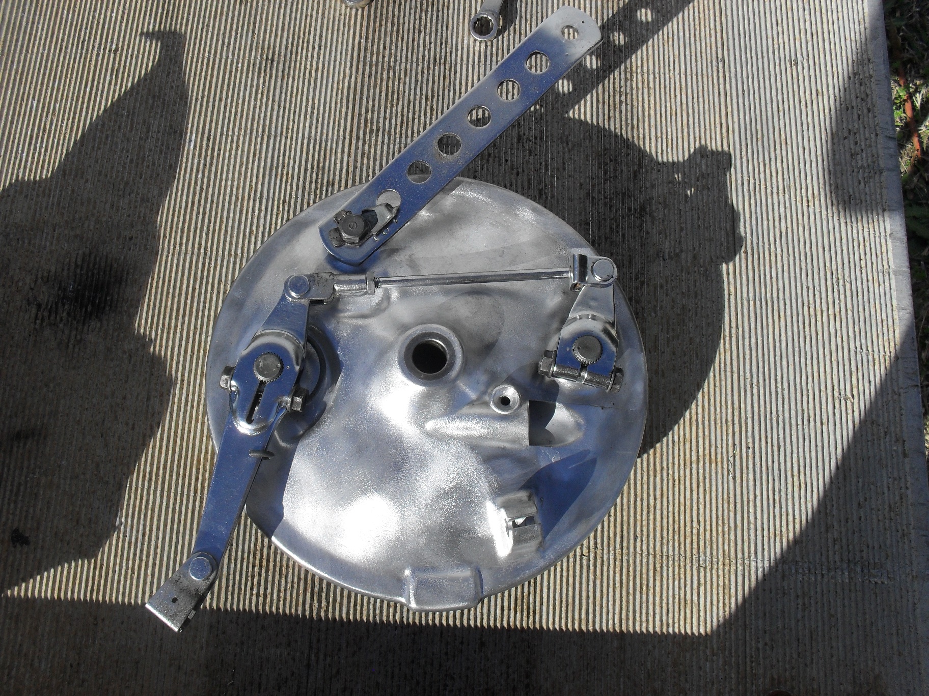
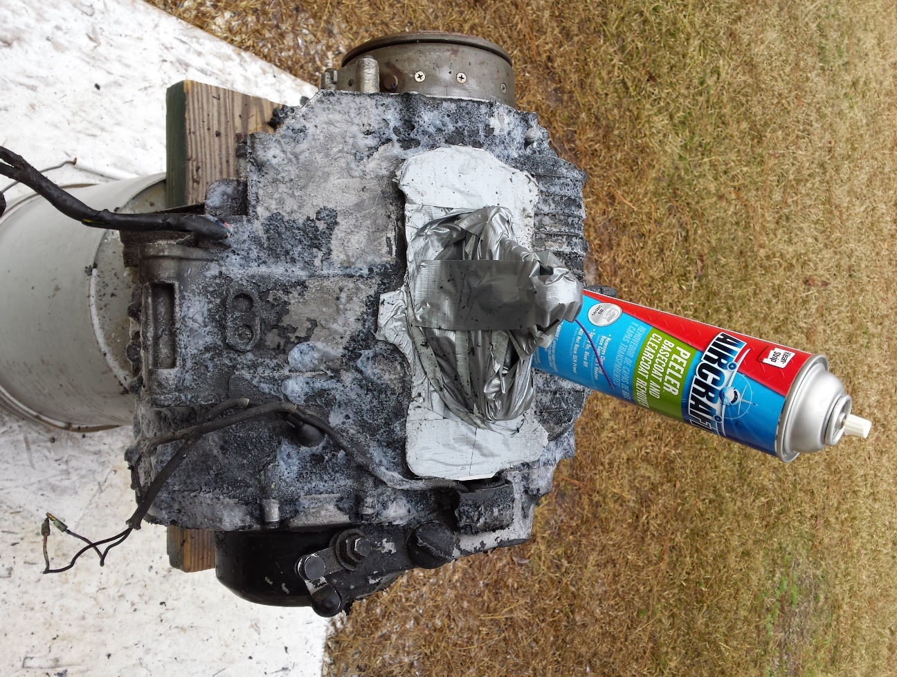
What we are going to look at today is an example of what may be the last of the of the factory installed twin leading shoe motorcycle brakes. The nasty cruddy looking part you see above is from an 81 Honda CM400E. The “E” stood for economy. The CB & CM variants of this bike got disc brakes on the front. By 1981 these were considered obsolete and were used on this model as a bit of parts bin engineering to meet a price point. This particular front wheel & brake backing plate had been painted at least 3 times in different colors What you see in the picture above is after using some aircraft peeler & some light soda blasting to clean it off a bit. Then I disassembled it and and dropped all of the chrome bits in the Metal Rescuetub and put the rest of it in the parts washer before wire brushing the backing plate. Please note, if you are doing a restoration you do not want to wire brush aluminum parts like this but this one is going on a rough edged custom and the brushed finish will be perfect for it.
This is an exploded view giving you a look at the typical parts of a front hub using this style of brake.
On this one I will not be reinstalling the speedometer gear as my plans call for a custom electronic speedometer. The first thing to do is apply a light coating of high quality grease to the shafts of the brake cams and push them into the backing plates.
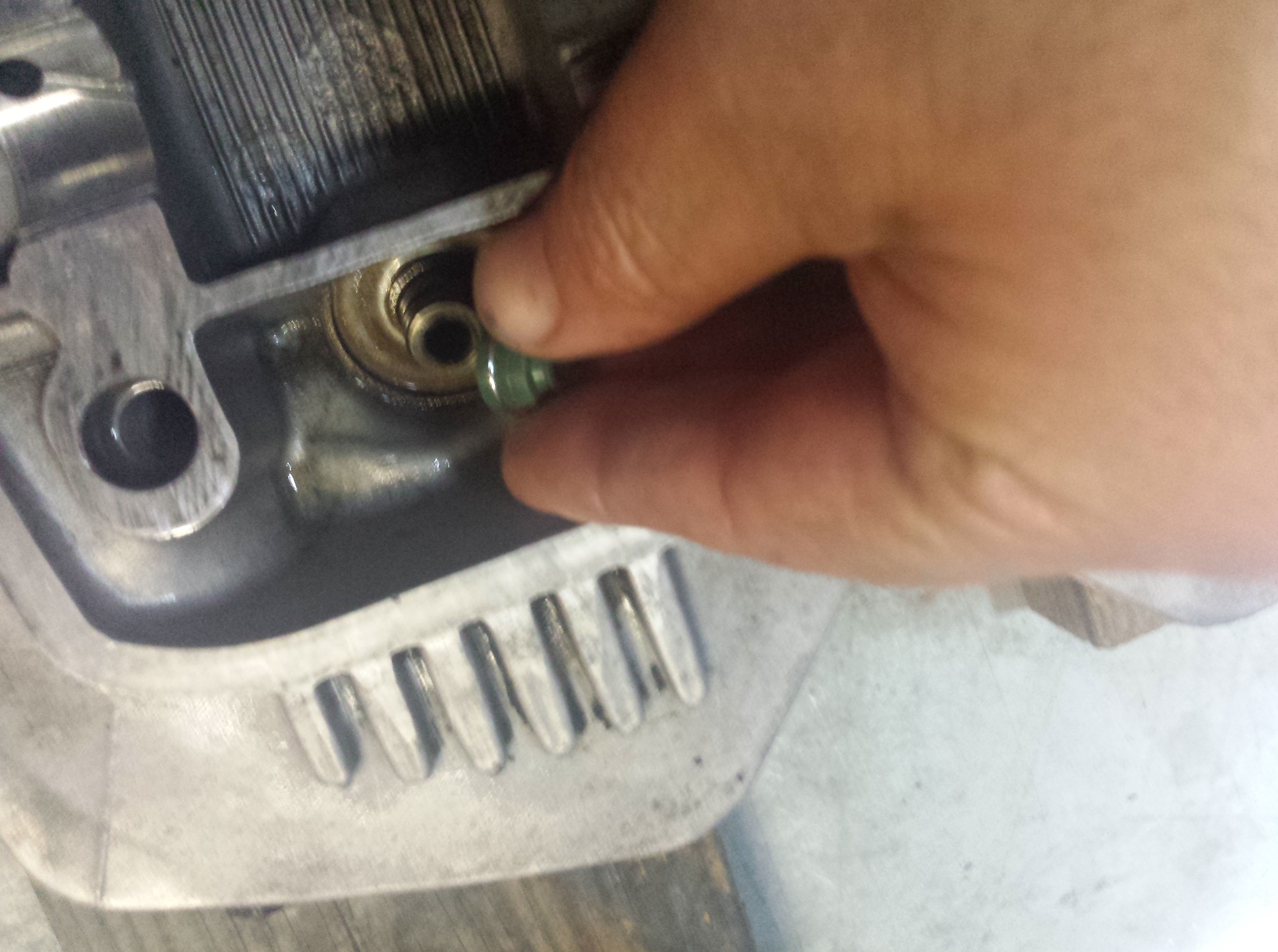
Second part is to put the clean, lightly oiled felt seals into place as illustrated below. While I am sure there is probably a specified oil for this I’ve always just used whatever was handy in my oil can and have never had any trouble. That being said I am not responsible for any trouble you may have if you do not research and use the factory recommended oil.
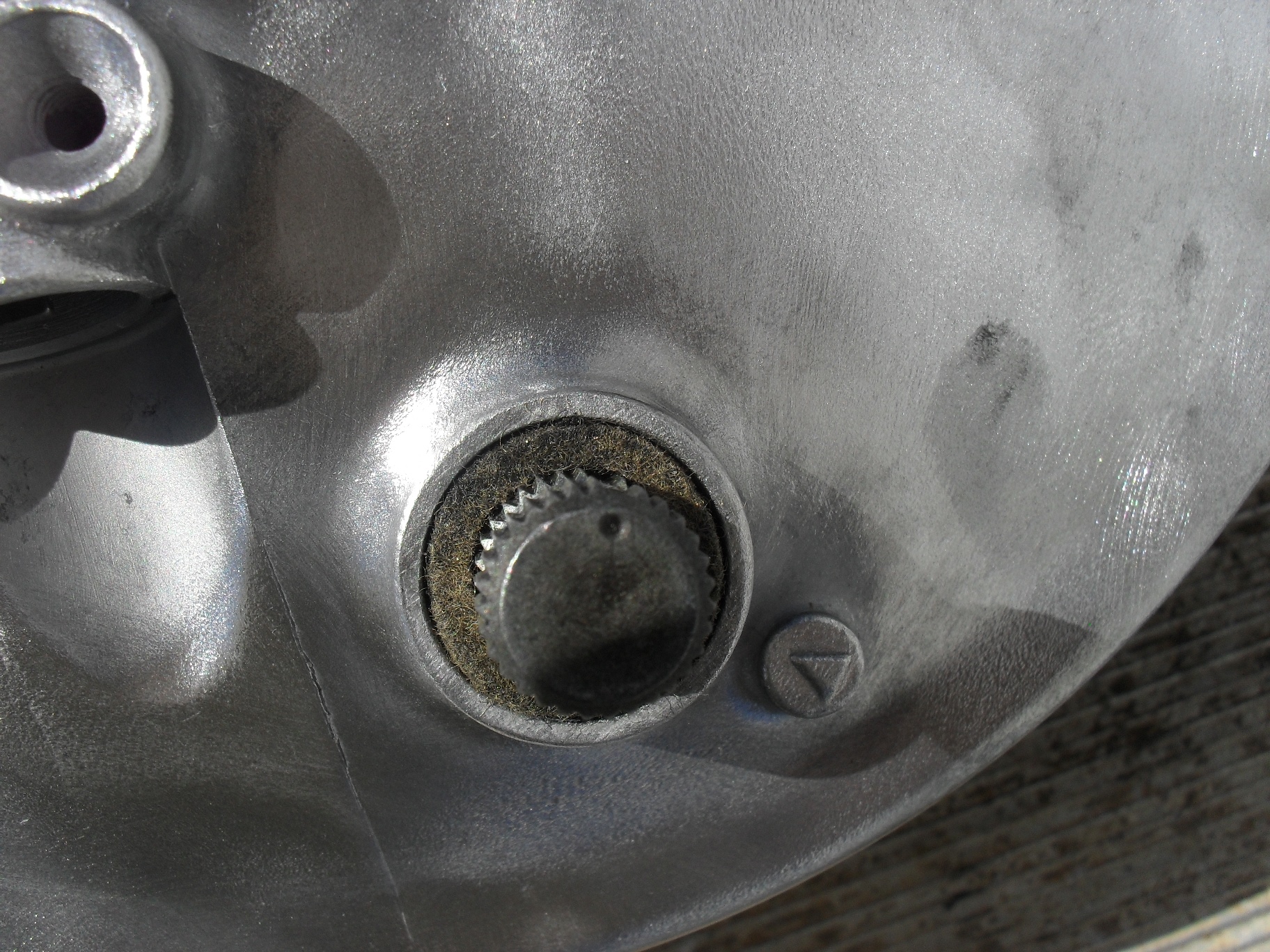
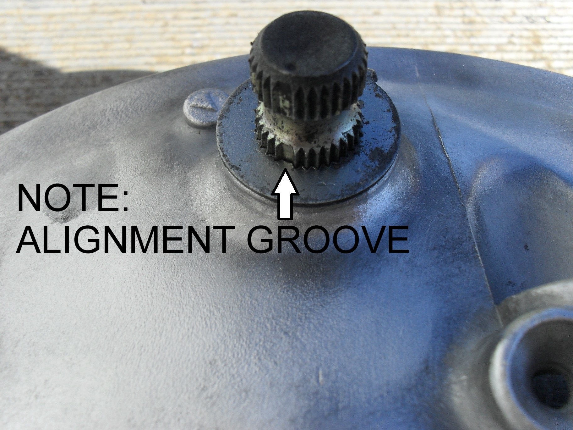
Third step here is to slide the washer with the wear indicator tab back down onto the brake cam over the felt on the side that you removed it from which should have a pointer cast into it like in the picture below. This little part has splines and has an alignment groove so that it will only fit one way. It it doesn’t just just slide back on you have it turned the wrong way and need to move it around the until the wide spline lines up with the wide groove.
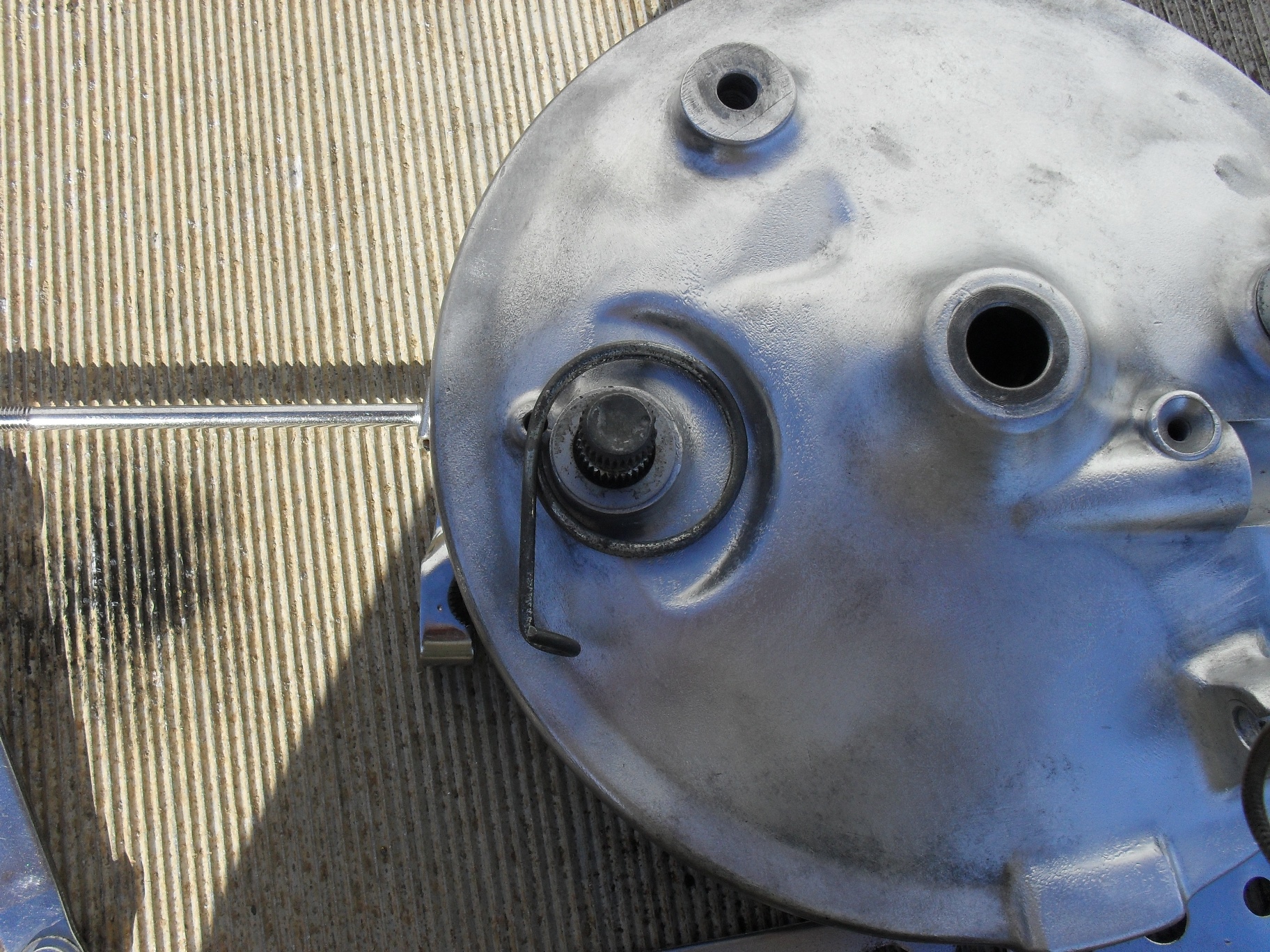
A plain thin washer slides down to cover the felt on the other side of the axle hole.
The external return spring is dropped into place next.
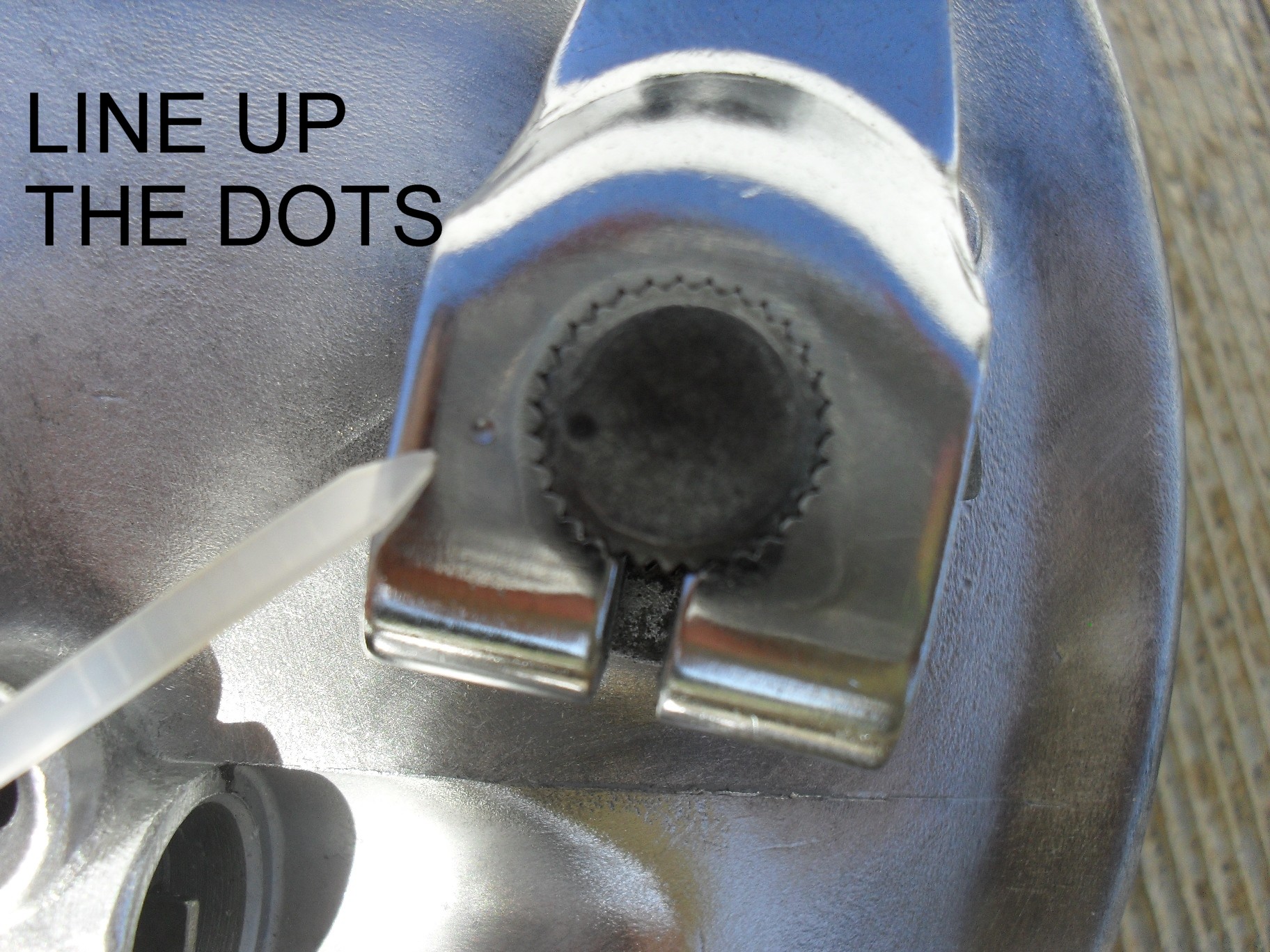
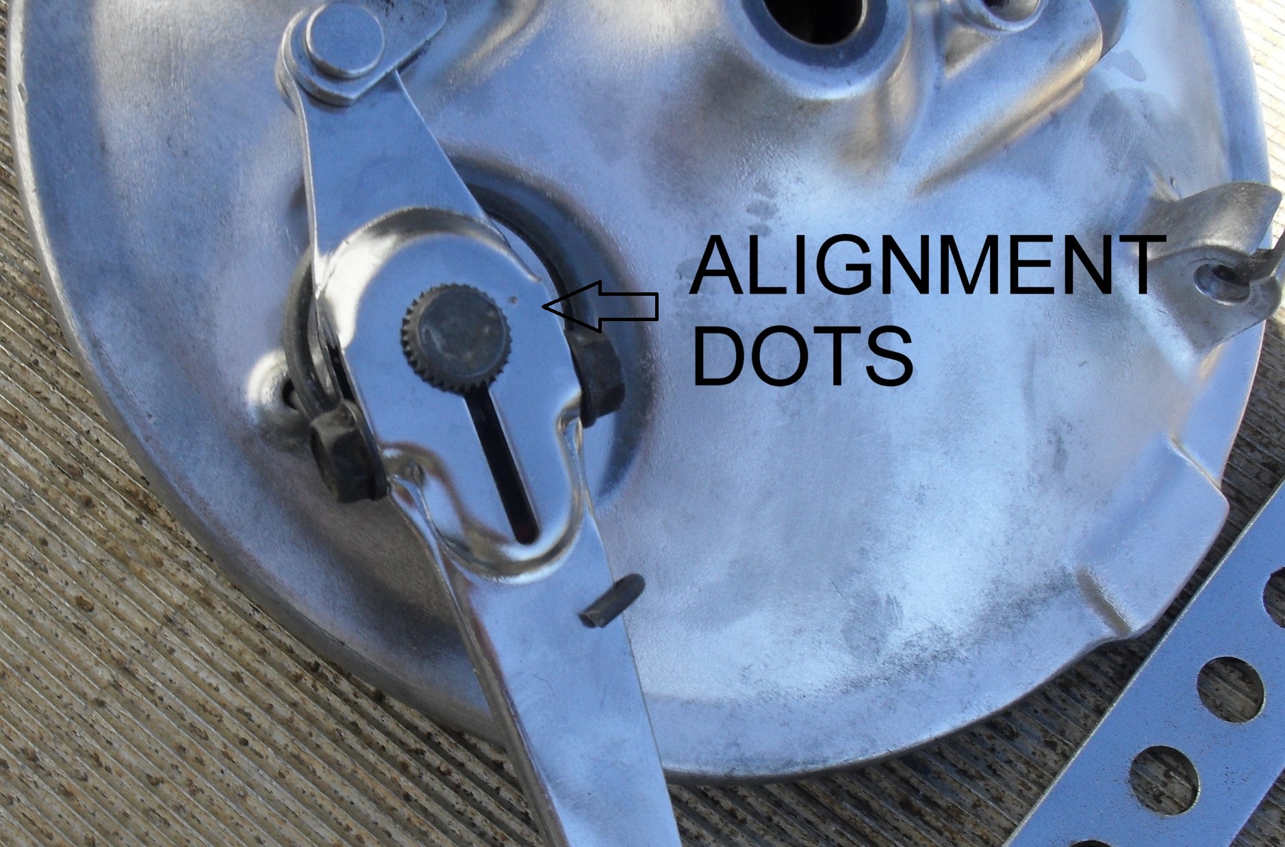
On of the really nice thing about most old Japanese bikes are the presence of dots on the brake cams & arms to help you line them up correctly the first time.
Put the arms on one at the time aligning the dots. I normally have brake rod loosely installed between the two arms before assembly just because I think it is easier than connecting the two brake arms afterward. If it is easier for you to do it the other way then that is fine too.
Do not tighten the lock nut on the brake arm yet! Install the brake shoes first!
Adjust the brake rod as necessary to get both shoes to move at as close to the exact same time as possible. If you are a real demanding performance nut build yourself a jig and use a couple of dial indicators to ensure that the pads are moving together exactly. For the vast majority of us eye-balling it will work fine and any teeny little mismatch that occurs will be wiped out within a couple of stops
Now you can tighten down that lock nut. Here’s a little video to show you how the cams move the shoes when the brakes are actuated.
Now its time to get to work on the rest of the front wheel so that it can be installed on the front of Project wAmmo!
For this ‘Psyco product review let’s checkout Workshop Hero’s Metal Rescue
rust remover. In the past I have always used good old phosphoric acid for removing rust. In fact I have a 15 gallon tank of the stuff carefully stored away for cleaning old gas tanks & stuff like that. It really removes the rust quite well but it is also toxic, smelly and will corrode the base metal while removing the rust. To use it requires rubber gloves and eye protection.
Last year at the VMA swap meet in Eustis Florida, I bought a gallon of Metal Rescue from a vendor and brought it home, then I poured some out in a small container & dropped a couple of extremely rusty parts in it and left them overnight. The next day they were a little better but not as good as I hoped so threw them into the acid tank and stuck the Metal Rescue on a shelf under the workbench until last month (January 2015).
I’m in the very beginning stages of ruining a wonderful dirtbike by restoring it, so I decided to try the Metal Rescue on some of the chrome bits that really needed cleaning up. First I got a good bucket large enough to hold the parts with a good fitting lid to seal it up and poured the entire jug of rust remover into it.
After waiting a day I opened it up and this is what I found, meh give it another day.
This is a picture of the same after 3 days, I am not a happy camper at this point.
So I pick up the jug to look for a way to file a complaint and read the part of the instructions that says; “For best results, use at room temperature (68°F or 20°C) or above. Metal Rescue™ works optimally at room temperature (68°F or 20°C) and above, so it may require heating in cold temperatures.” Looks like using it in an unheated shop in January is out of the question unless you live closer to the Equator than I do or on the opposite side of it.
Determined to get my money’s worth out of this product I carried the bucket into the house and put it in the laundry room to warm up. When I checked on it the next day 90% of the rust was gone and on the fifth day of soaking the heat shield looked like this!
The rust was completely removed from both sides and I was very impressed. It probably would have helped a lot if I had read the instructions first. Since then I just keep this bucket of Metal Rescue in a safe place in the house. It is chemically safe with no hazardous ingredients and if you take care to ensure that no hazardous substances get into it, Metal Rescue can be safely disposed of in most sewer systems but check your local laws first.
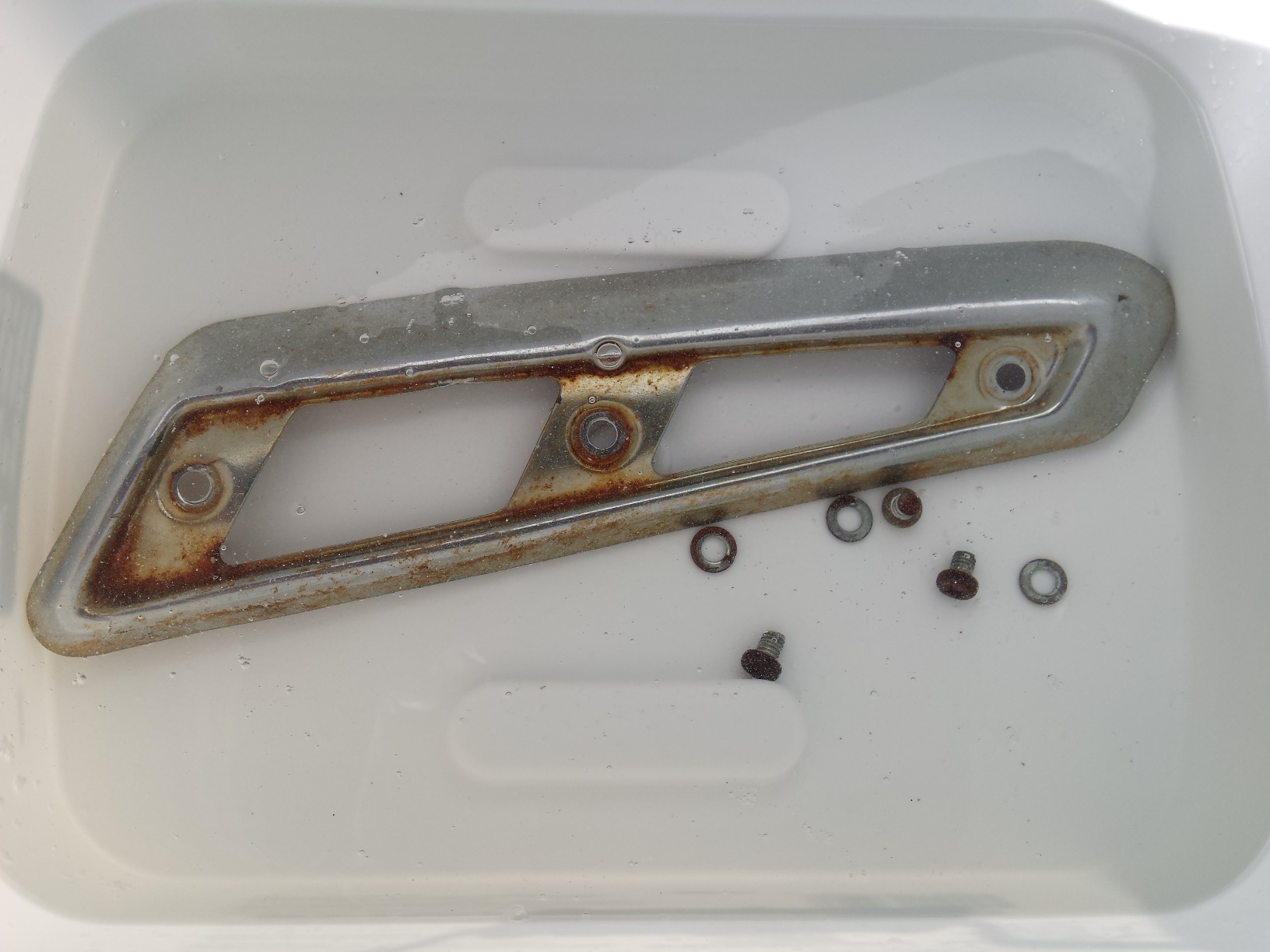
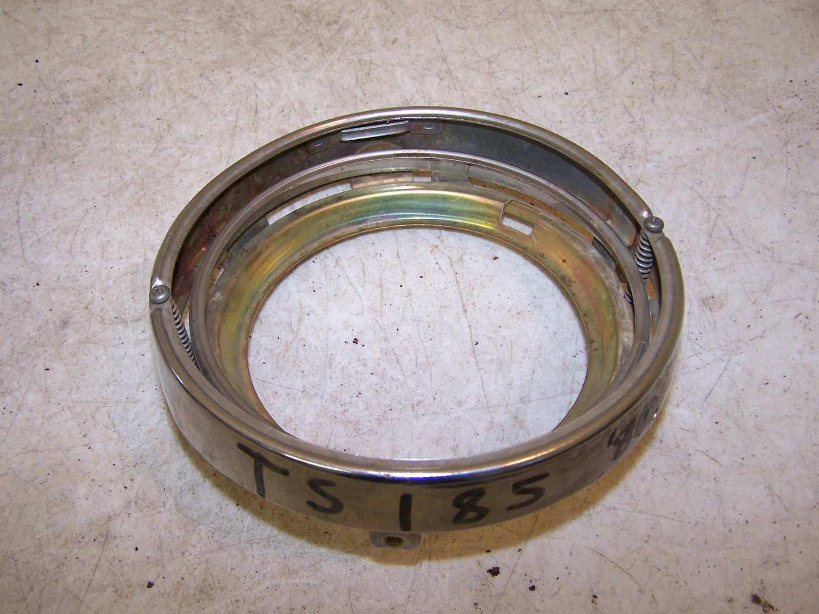
To give you an idea of how much I like this product, I bought some more and put it into the bucket with what I already have. With the solution at room temperature it took less than 24 hours to clean up this headlight ring to the condition that you see here. Plus I was able to leave it assembled with all of the plastic parts & springs while it soaked something you would not dare do with acid.
The instructions do warn that if you leave plain steel parts in the Metal Rescue
too long that it will turn them dark after removing the rust. Plated parts don’t seem to be affected by this. The screws in the picture below illustrate this. Since I am going to be re-coating these screws it’s not an issue for me, but if you are restoring something that calls for a natural metal finish you should be aware of this.
What’s the bottom line, is it worth 25 -30 bucks a gallon? Yes, especially when you consider that if properly stored it can be used over & over combined with the fact that it is biodegradable and contains no VOCs, solvents, acids, bases or hazardous ingredients. Just be sure you read the dadgum instructions on the jug first. It really does work much better when it is warm.
Peace Y’all
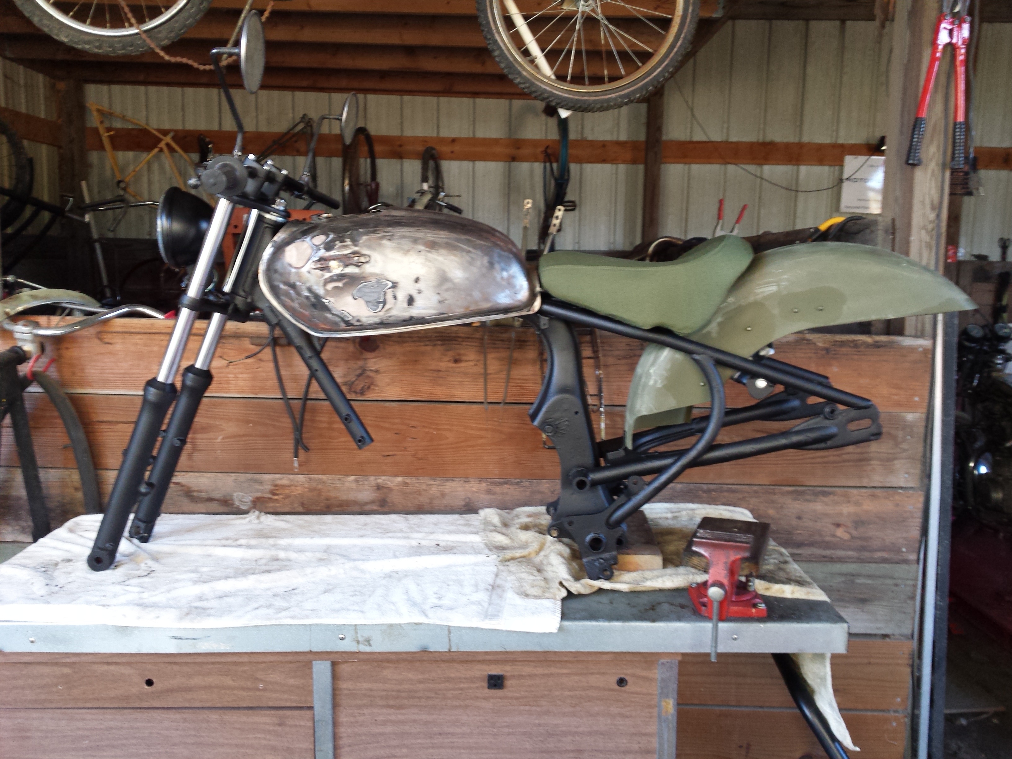
It’s time for another Project wAmmo CM400 update. Let’s start with my confession that I lost interest in the project for a little while and was really short on time for it. Had some issues with getting the frame sandblasted so I wound up bringing it back home and hit the frame with some paint remover and went over it with my little hand held sandblaster before coating it with spray on truck bed liner. Did the same thing for the tank before brazing up a couple of damaged spots on it and sealing it with Caswell Epoxy Gas Tank Sealer. I also wound up replacing the fork because I was unable to identify the one that was on it to get the proper repair parts so I replaced it, and installed a set of tapered roller steering head bearings for good measure.
I got the modified Harley solo seat covered in olive drab Cordura fabric to match the overall theme planned for the bike.
Even though the engine would start and run okay, compression on the right cylinder was consistently 50 psi less than the left cylinder. Even after adjusting the valves (click here for the proper procedure) which didn’t help, and putting some oil in the cylinder to see if it would come back up temporarily indicating worn rings, the right side was still 50 psi lower than the left side so I went ahead and pulled the engine apart for a top end overhaul.
The problem turned out to be that the oil rings were frozen to the piston and the gaps were aligned on the top 2 rings preventing them from sealing. The downside to this bike originally being such an artistically created “natural” ratbike is that it was incredibly nasty. Here I am soda blasting the cylinder to clean it. Yes that is the cheap hand held sandblaster
and it works just fine with blasting soda, so if you’re on a budget & just need to clean a few small parts without damaging them the way sandblasting can try this. Just do not hit any gasket mating surfaces with the soda.
Once everything was cleaned & honed I taped off the mating surfaces so that I could spray on some Duplicolor cast iron gray engine paint.
The original clutch cover will be replaced with this good used one and since I was not splitting the cases for a full overhaul I sealed up the bottom half of the engine with duct tape so that I could degrease it and remove the existing paint.
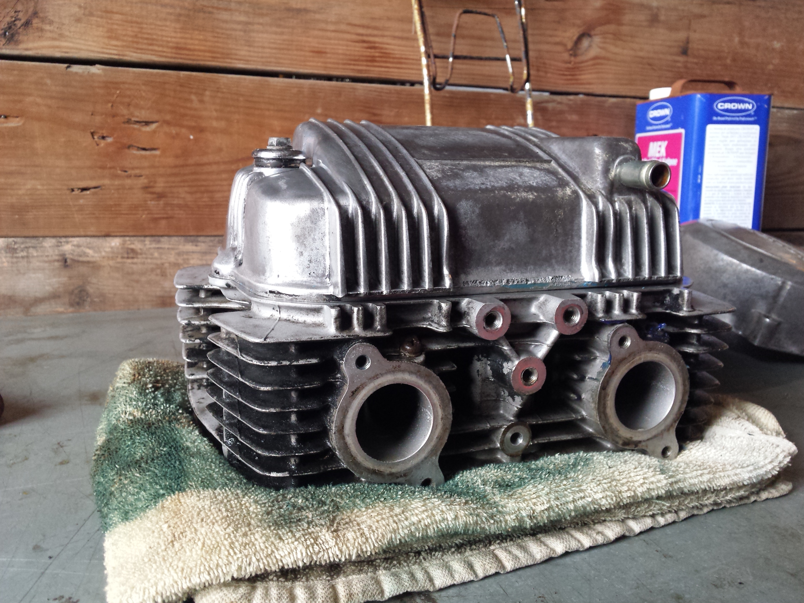
Since the head needed a good clean up, it became the subject of a head service tutorial that you can read by clicking here. The next picture is of the original pistons with new rings ready for the cylinder to be re-installed. The blocks of wood held the pistons up and level while beautiful assistant slid the cylinder slowly into place while I compressed the rings.
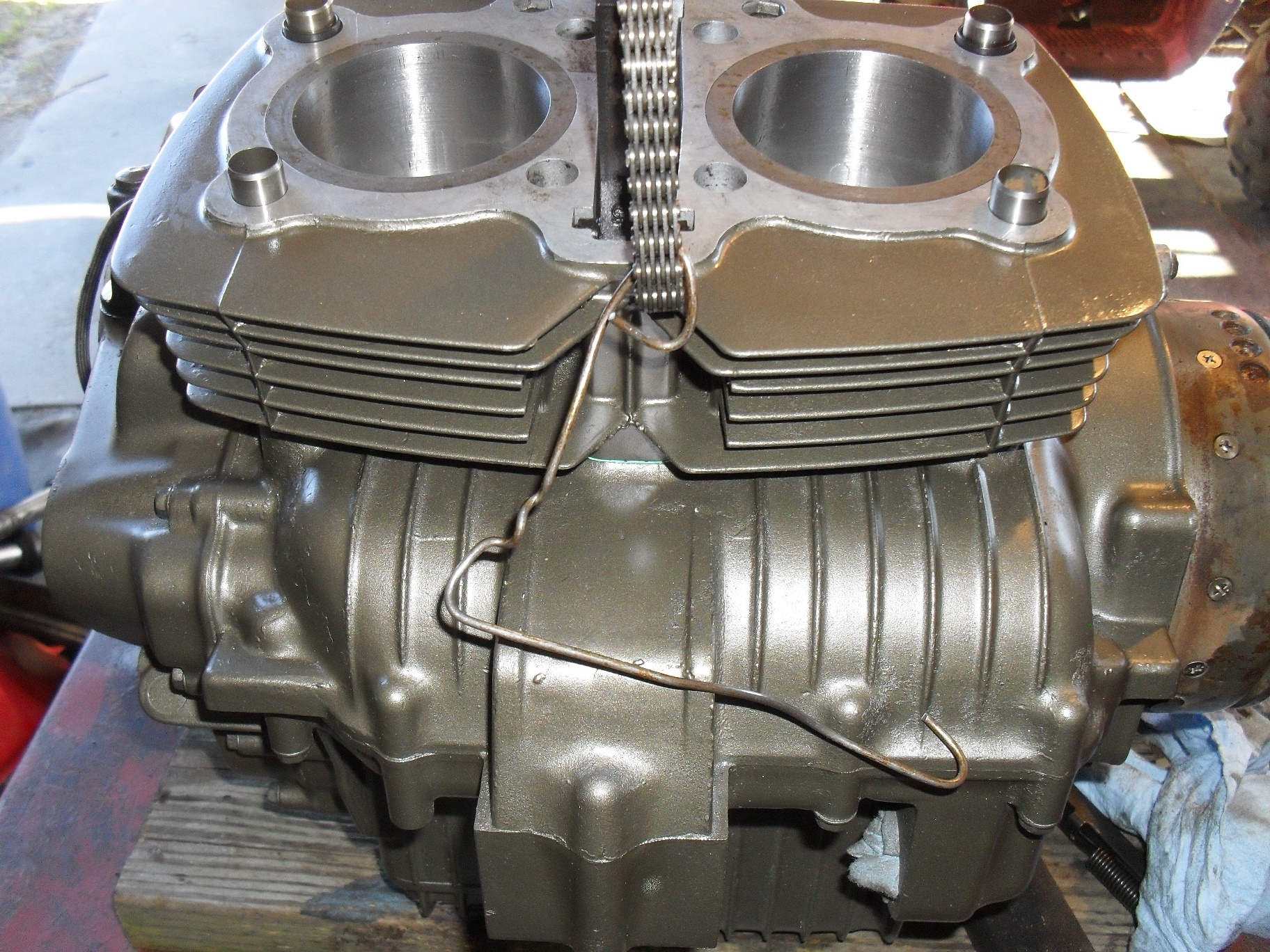
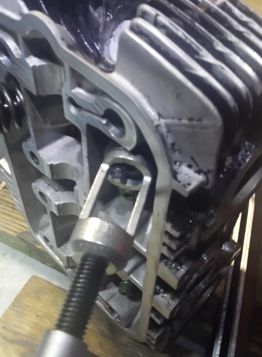
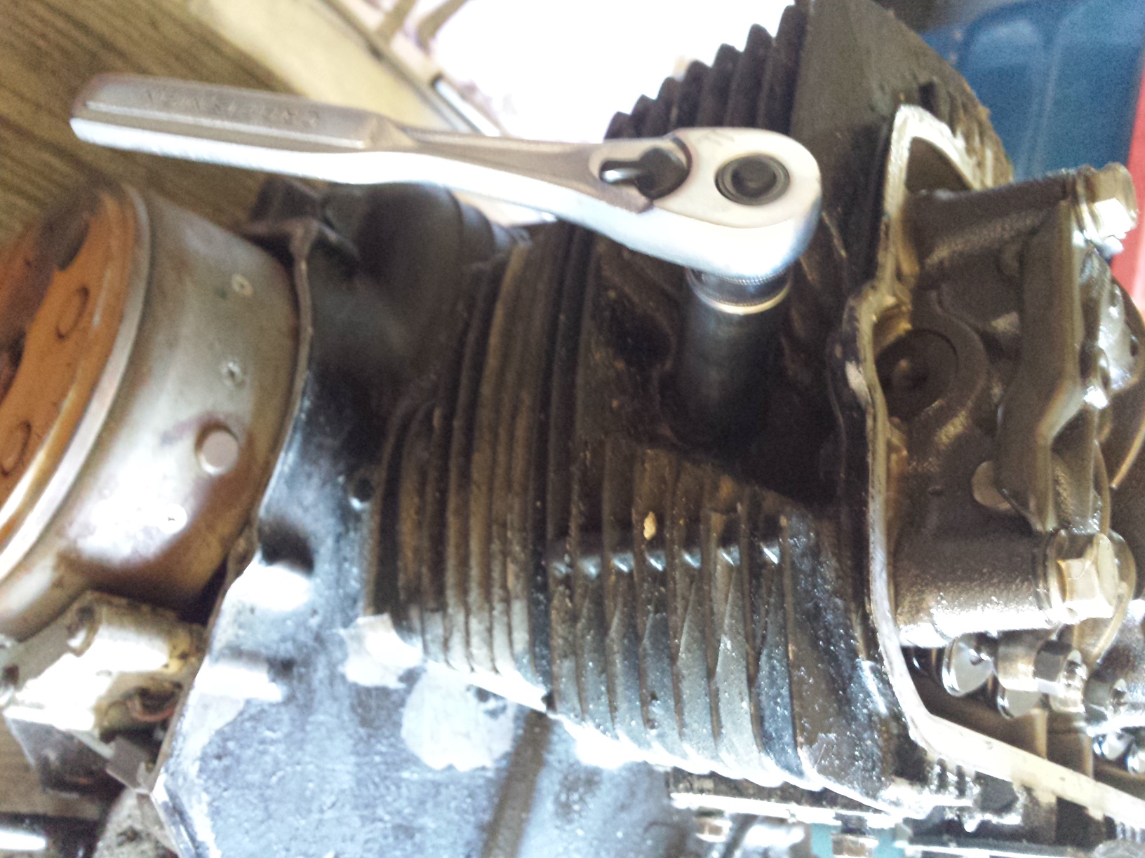
This looks a lot better than the before picture doesn’t it? Once I got the head back on it was time to line up the timing marks for the crankshaft & camshaft as shown below and put the camshaft back in.
Afterwards it was just a matter of putting the rest of the parts back on and torquing everything down properly. Don’t forget to fill the oil pockets under the cam lobes with oil before putting the rocker box cover back on.
The engine is now ready to reinstall, I am going to leave the rotor cover off until later, ditto for the new clutch cover.
Now the engine is sitting back in the frame. The intake spigots are new replacements for the damaged originals.
I like puzzles
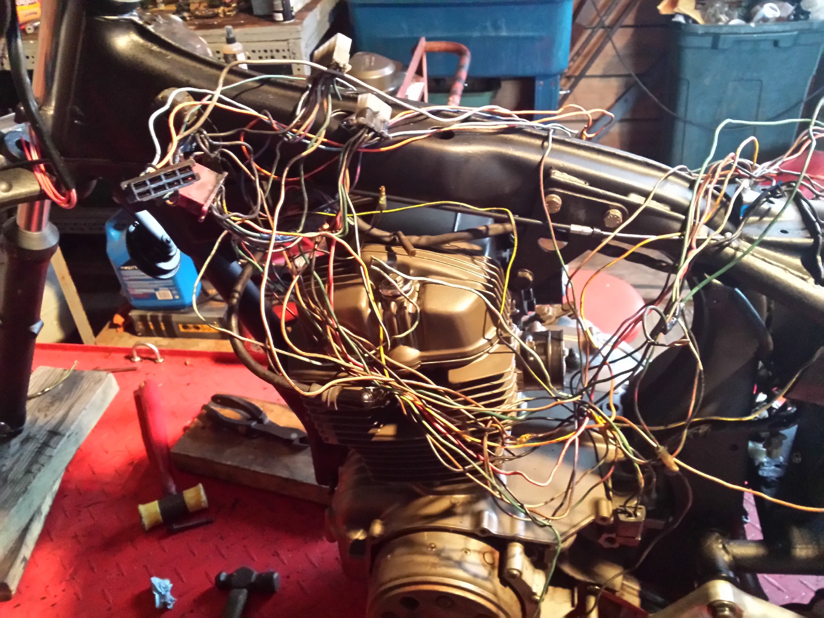
Now its time to sort out the wiring harness. Sometimes it is easier to start from scratch but for right now I am going to attempt to reuse at least some portions of the factory harness.
Normally on a custom motorcycle one would attempt to hide such parts as the regulator rectifier but since I am going for a post apocalyptic paramilitary look on this machine it is bolted to the side of the rear fender out in plain sight.
Once I get the wiring sorted out and get the wheels back on it’ll be time top restore this set of CV carbs. I will probably do an in depth post on that process when the time comes.
Yes I know dear reader, I skipped the WOTM feature in January, it flew by in a hectic rush of past due deadlines and impossible promises. For the first one of the new year, I am going to grab some low hanging fruit. This is absolutely one of the most entertaining websites on the planet; The Selvedge Yard. Many a pleasant hour have I passed perusing it’s vast archive of pop history with regards to music, racing,celebrities, art, & motorcycles.
A HISTORICAL RECORD OF ARTISTRY, ANARCHY, ALCHEMY & AUTHENTICITY.
Don’t take my word for it, go check out The Selvedge Yard, I promise you will have a good time!
It’s time once again for the one of the premier shows on the Vintage Japanese Motorcycle Club calendar; The Destination Eustis Vintage Motorcycle Show! I attended this show last year and although I am unable to attend for this year I was so impressed that motopsyco.com is one of many fine sponsors of the event this year. At this time I am definitely planning to return in 2016.
Please note that just because this is a VJMC show does not mean only Japanese bikes, Bring out any old iron you have be it American, British, or European there are classes for everything as long as it is vintage!
Just a reminder that this Vintage Motorcycle Show will take place inside the Lake County Fairgrounds EXPO Building. It is a secure facility with the ability to load and unload motorcycles inside the facility in the event that it rains. This is a premier VJMC show venue. There will be no Bike for Sale signs on any bike entered into the show. Also only bikes entered in the show will be displayed in the main expo building.
Here’s a little walk through of last years show to give you an idea of the quality of machines you can expect to see there.
The International Motorcycle Swap Meet and Vintage Motorcycle Show is taking place at the Lake County Fairgrounds in Eustis, Florida March 6-8, 2015. This year’s event continues a legacy of more than 20 years of vintage motorcycle events at this location. We would like to thank the City of Eustis for graciously supporting this event. Once again they will host in our honor a Downtown Block Party on Friday evening, March the 6th. On Saturday, March the 7th local business will provide entertainment and local restaurants will open their doors for all event attendees. So come join us as share our event with the City of Eustis and their local businesses.
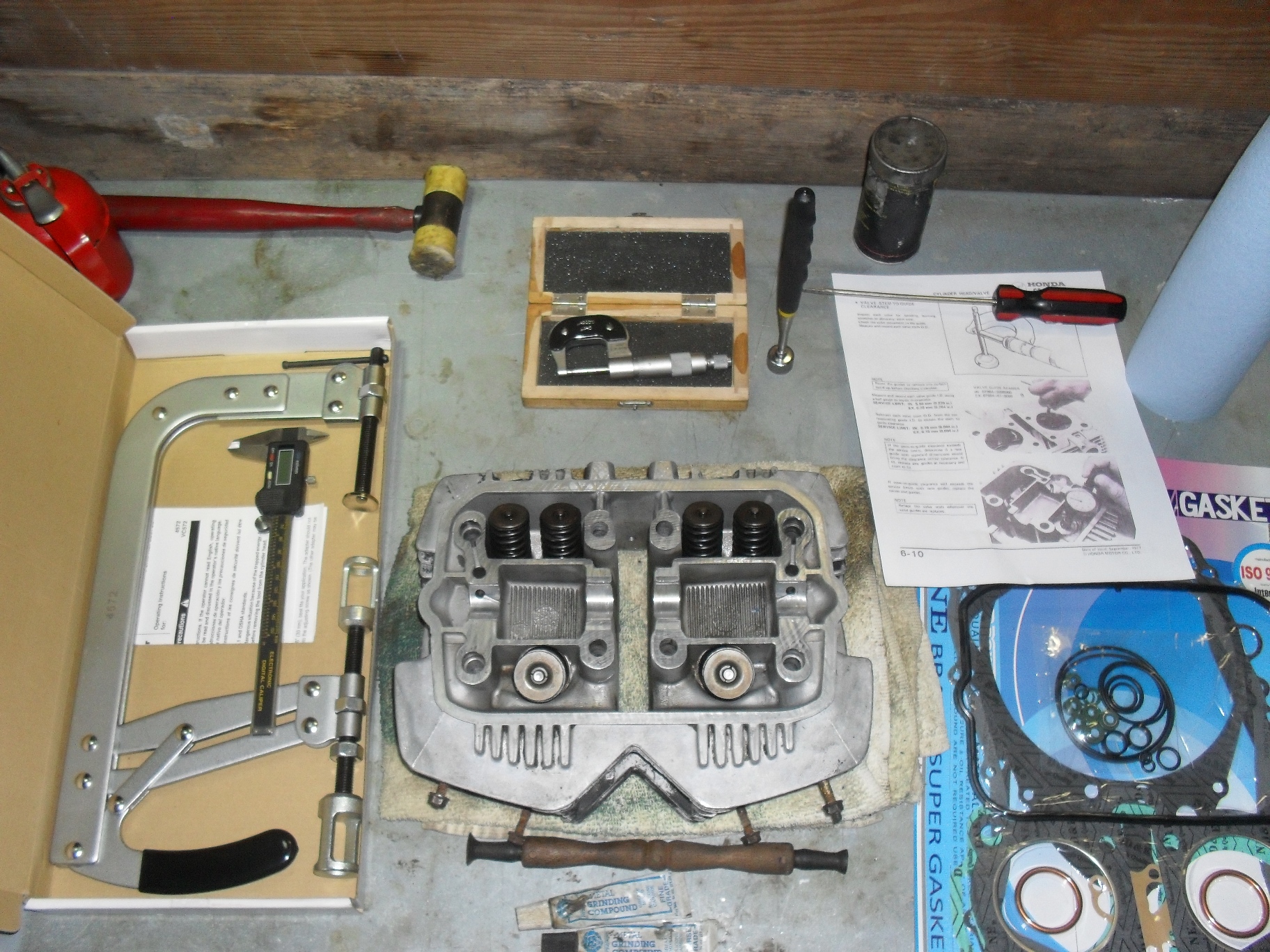
D.I.Y. motorcycle head service is possible for the home mechanic at times, under the right circumstances. Of course if you are one of those fortunate individuals who happens to have a fully equipped machine shop and know how to use it you can do anything. But for the ordinary person restoring an older motorcycle or atv that wants to save a buck or two it is still possible to do an acceptable job provided certain conditions are met.
My patient for this job will be the CM400 that I used for the valve adjustment tutorial a couple of weeks ago. After adjusting the valves and putting oil in the cylinders it still had about a 45-50 psi difference in compression from the left to right sides so I pulled it apart for a top end overhaul. It turns out that the right cylinder had oil rings that were stuck from sitting and that the gaps were aligned on the other two rings.
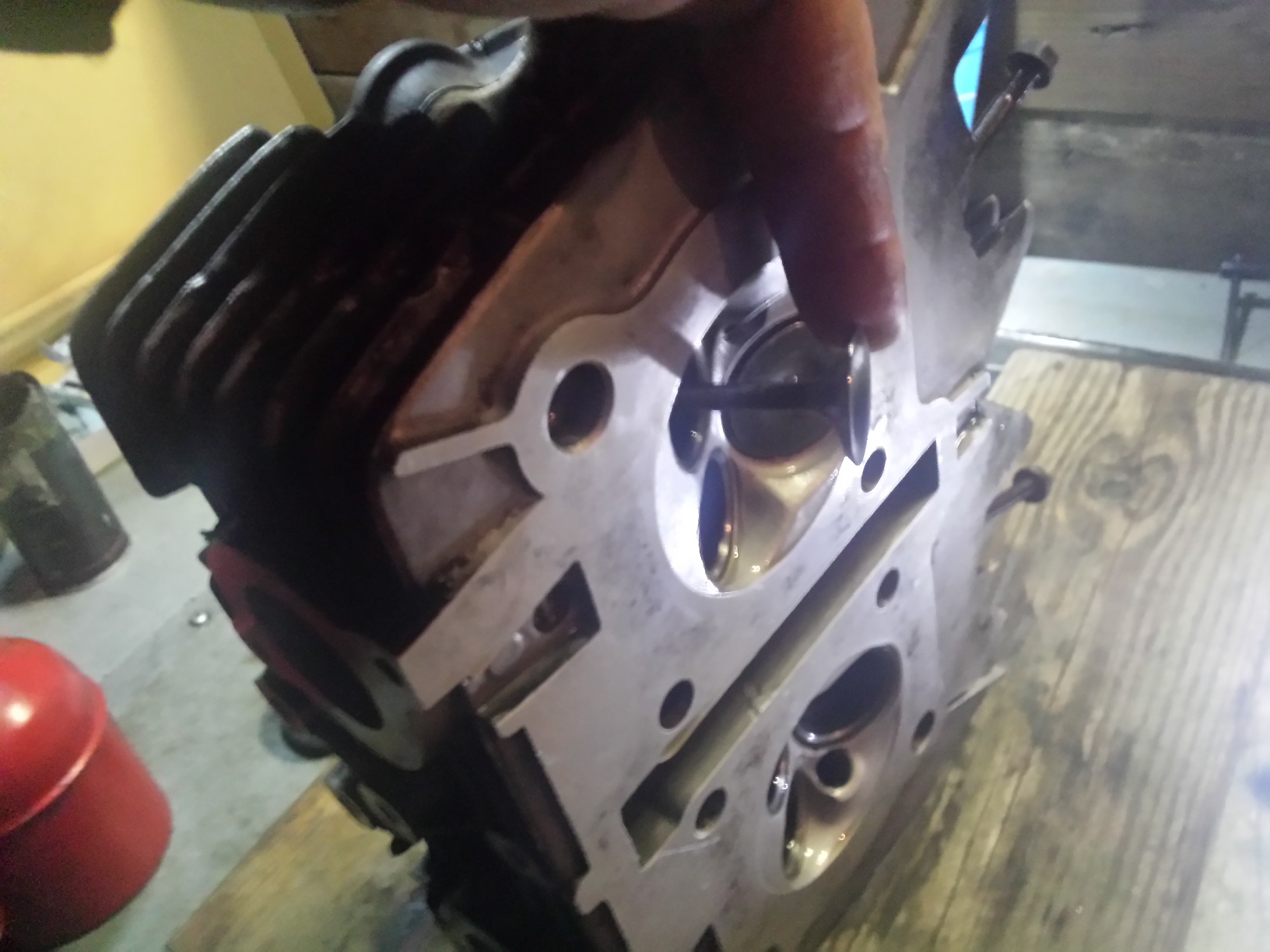
Before disassembling it, I cleaned the head fairly well and removed the carbon from the combustion chambers. This makes handling the parts much nicer and inspection much easier. No matter what method you use to remove the carbon do not allow any type of abrasive or wire brush or scraper to contact the flat sealing surface of the head. Yes I know you may have to use some type of scraper to remove the gasket residue from the head but be very careful not to scratch or gouge it in any way. I actually used soda blasting to clean this head but made sure not to hit the mating surfaces with it.
Now I must make a couple of quick disclaimers here. First there are some defects that if discovered during the inspection process that will mean you need to take your head to a machine shop to be repaired anyway. Second, unless you own a set ball micrometers to check them with, you will basically be guessing that the valve guides are okay based on the condition of the valve stems. Chances are that if like me, you are working on something old but with relatively low mileage they are okay BUT it is not guaranteed and excessively worn valve guides can cause oil consumption & smoking even with new seals. Third, this is not the high performance option, if you are building a hotrod and looking to squeeze every last drop of performance out of it you can then I suggest you contact a reputable high performance machine shop for a good 5 angle valve job and new valve guides. This is to get your old heap running as good as possible for the least amount of dough you can spend. The fourth and last disclaimer is to always put safety first in the shop. You will be dealing with strong springs under compression. There is a chance that a tool could slip releasing a spring to go flying out at high speed and hit you or to pinch your fingers between the spring & the tool. Only use a good quality valve spring compressor
in good condition, make sure you read the instructions that come with it, & wear some eye protection too.
Even so there are some specialty tools you will need to get if you do not have them. In the picture above at the bottom center the thing with the two suction cups on it is a valve lapper with 2 tubes of grinding compound one coarse & one fine. Moving clockwise around the head are the valve spring compressor, a caliper dial or digital whatever you have, a light rubber or plastic hammer just in case something needs a tiny bit of extra persuasion, a micrometer (if you don’t know how to read a micrometer you can either learn how or just buy a digital one.) Next item to the right is a pick up magnet and a flat screwdriver, a few pertinent pages photocopied from the service manual and a new gasket set with valve seals. If you want to learn to use a micrometer watch the 2 videos below.
Set your valve spring compressor into place over the first valve you wish to remove and turn the compression screw inward until the spring is compress enough that the valve keepers either fall out or you can reach in with a magnetized screwdriver and pull them out.
It is very important that you keep your valves, springs, & other parts together so that they can be reinstalled in the same opening from which you removed them. This is especially critical for the valves as they wear into their valve guides and seats as the engine is operating. If any of the valves do not come out, or if removal is difficult you may have a bent or seized valve, put everything back together and find a good machinist. The cure for a damaged valve requires replacing the valve & seat as a unit. The valve guide drivers and reamers required for this job are really a bit much to purchase & learn to use for just one head.
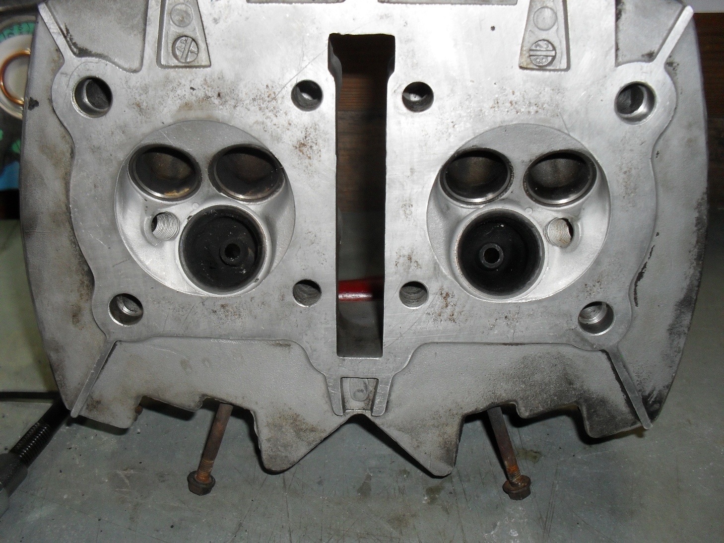
Once you get all the valves out give the head a good visual inspection looking for anything that looks galled, burnt, or cracked
Be sure you check inside the ports to especially around the valve guides. Next check the valve seats which are the hardened steel inserts around the outside of the large holes in the combustion chamber. If any of valve seats 0r guides are burnt, badly scored or pitted , have cracks in them or easily visible excess wear then you need to put it back together & take it to a competent machinist
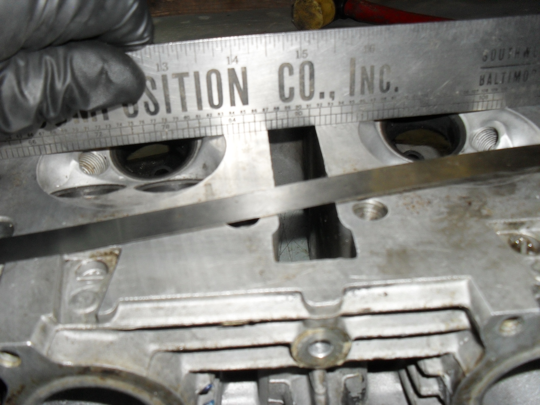
If all looks good make sure the head is not warped beyond acceptable limits. for this you’ll need a good straight edge and a feeler gauge in whatever size your service manual specifies
Place the straightedge firmly across the head in several locations and try to insert the feeler gauge between it and the heads gasket mating surface. If it goes between the two anywhere then a machinist will need to shave the head to level it back out.
Now it’s time to grab the micrometer and check the diameter of every valve stem in several places up & around each one. If any of them are worn beyond the service limit, chances are the valve guides are shot too and this is no longer a normal do it yourself job. Double check them for straightness at this time also,
After that get a caliper and measure the extended length of all of your valve springs. Replace any that do not fall into the specified range for your motorcycle.
Once the inspection process is complete and you are satisfied that all of your parts are in good condition & can be reused go ahead & clean the valves & guides thoroughly. Most of the time you can just scrub the intake valves clean in the parts washer, but the exhaust valves usually have a hardened scale stuck to them so I use a brass wire brush to clean them with. For the valve guides I use a gun cleaning brush, but any small round brush with plastic or brass bristles that fits through them will do. I try to avoid using brushes with steel or stainless steel bristles on parts like these because I only want to remove the grease, carbon, and scale without affecting the base metal.
Pick out whichever valve you want to start with and put a small amount of valve grinding compound around the head of the valve on the surface that contacts the valve seat in the head, and place that valve back into the hole that it was originally removed from. Grab the valve lapping tool & stick one of the suction cups on it to the valve like this and then rotate it back & forth to clean the mating surface. The most efficient way to do this is to hold the lapping stick between your palms and pretend you are trying to start a fire with it. Stop occasionally to check on your progress and replenish the lapping compound if needed. I use a coarse compound to start with & then switch to fine grit, but it is possible to make do with just the fine grit if that is what you have.
Stop and inspect rather frequently, you are not trying the grind the entire surface of the valve & seat flat. What you want is a uniform,well polished shiny ring all the way around the valve & seat at the point where the two meet. Once you have that, to keep polishing is just putting unnecessary wear on your engine parts. It should only take you a few minutes per valve to accomplish this, so keep going until you have all of the valves done.
With all of the valves lapped you now need to wash them and the head again and completely remove all of the valve grinding compound so that it doesn’t make its way into your freshly overhauled engine and grind up parts that don’t need it. Then open up your gasket set and find the valve seals. I have the seals for this engine laid out above.
The two larger one are for the exhaust valves and the four smaller ones are for the intake valves.
Once you have all of the seals into place it is time to start reinstalling the valves remembering to put each valve back into the hole that you removed it from to start with. First push the valve back into the hole.
It should go in smoothly, make sure that it doesn’t push the new seal off of the valve guide. Put the matching valve spring(s) and retainer back into place over the valve stem.
You will have to carefully hold the retainer while you put the valve spring compressor into place to compress the valve spring(s).
Compress the springs until you can see the grooves for the valve keepers well enough to reinstall the keepers.
Put a thick coat of grease on each retainer to stick it to the valve stem when you put it into place.
If at all possible use a pair of tweezers or needle nose pliers to put the keepers on the valve stem. If you find that you must use your fingers to get them both into place be extremely careful and make sure that the compressor is securely clamped and not going to suddenly pop loose and crush your fingers while you are positioning the keepers. You have been warned.
When you have the keepers in place on the valve stem then slowly unscrew the clamping screw and if necessary keep the springs and retainer straight as you release the pressure. Remember if your compressor has a release handle on it like mine does, do not use it to clamp & release the valve springs. Always use the clamp screw. The release handle is there to allow you to move it from one valve to another without having to fully unscrew the clamp every time. When you have fully released the pressure & moved the clamp your vale should look like the picture below with both keepers trapped securely between the retainer & the valve holding the whole lot securely together.
Repeat these steps until all of your valves are securely reinstalled in the head.
I have tried to be as honest as possible with you about the possible pitfalls and risks of D.I.Y. motorcycle head service, but if you are willing to take your time, check everything carefully, and work in a meticulous fashion there’s no reason that you cannot give it a shot. Just be willing to take the risk of trying on your next restoration or overhaul and you’ll find yourself having that much more satisfaction with your handiwork once the engine is up and running.
Of course since I want this one to look as good as it works I covered up all of the mating surfaces & plugged all the ports before spraying my favorite ceramic filled engine paint on it. If you need tools and supplies just visit my webstore’s tool sections and search for what you need. If you can’t find something there let me know & I will point you in the right direction even if it means sending you to someone else.
I love cheap tools sometimes. My own personal collection is a mixture of top name brands and some of the cheapest shit you can find that actually works. Surprisingly sometimes the cheap stuff is better than the expensive stuff in some applications. It doesn’t happen often but occasionally it does. Most of the time you get what you pay for though and here in a tale of 2 valve spring compressors I’m going to show you a great example of this principle in action. As I started to tear down the head for the CM400 I am overhauling I realized that none of the valve spring compressors that I already own would work, 2 or 3 of them were for side valve engines, one was your typical auto parts store V8 compressor & the last one is a homemade thing especially made to work on old Honda 50-200cc dirtbike engines. Of course none of them would work, what I needed was one of the large C-clamp style tools with multiple adapters like all the shops that I used to work at had. So I came inside, fired up the computer and went shopping.
Of course I did not start out looking for the cheap stuff, my first search was for a genuine Motion Pro Valve Spring Compressor
but it is a bit pricey at around 100 bucks or so not including the Motion Pro Adapter and Bore Protector Set That being said if you got the money to throw around or if you are running a full time professional shop it is the best one to get.
Being in an experimental state of mind (okay that’s bullshit I am just a cheap bastard sometimes) I decided to try out this one that is all over ebay & Amazon for around $30 dollars shipped. It came in a nice molded plastic box with plenty of adapters for different size valve springs.
…
Unfortunately the cheap thin wall tubing that it was made of almost immediately began to flex and fail without budging the valve spring in the slightest. All of the compressors of this style & price range had very mixed reviews on the various merchant websites where they are sold apparently they work on some engines with weaker springs but on this head it did not work at all and was in fact a complete & total failure.
Have your balls ever fallen out?
To add insult to injury one of the balls that retains the adapters to the tools popped out of its socket
As you can see here this Stark valve spring compressor is now permanently bent and no longer fits back into it’s slot in the case. Back for a refund it went!
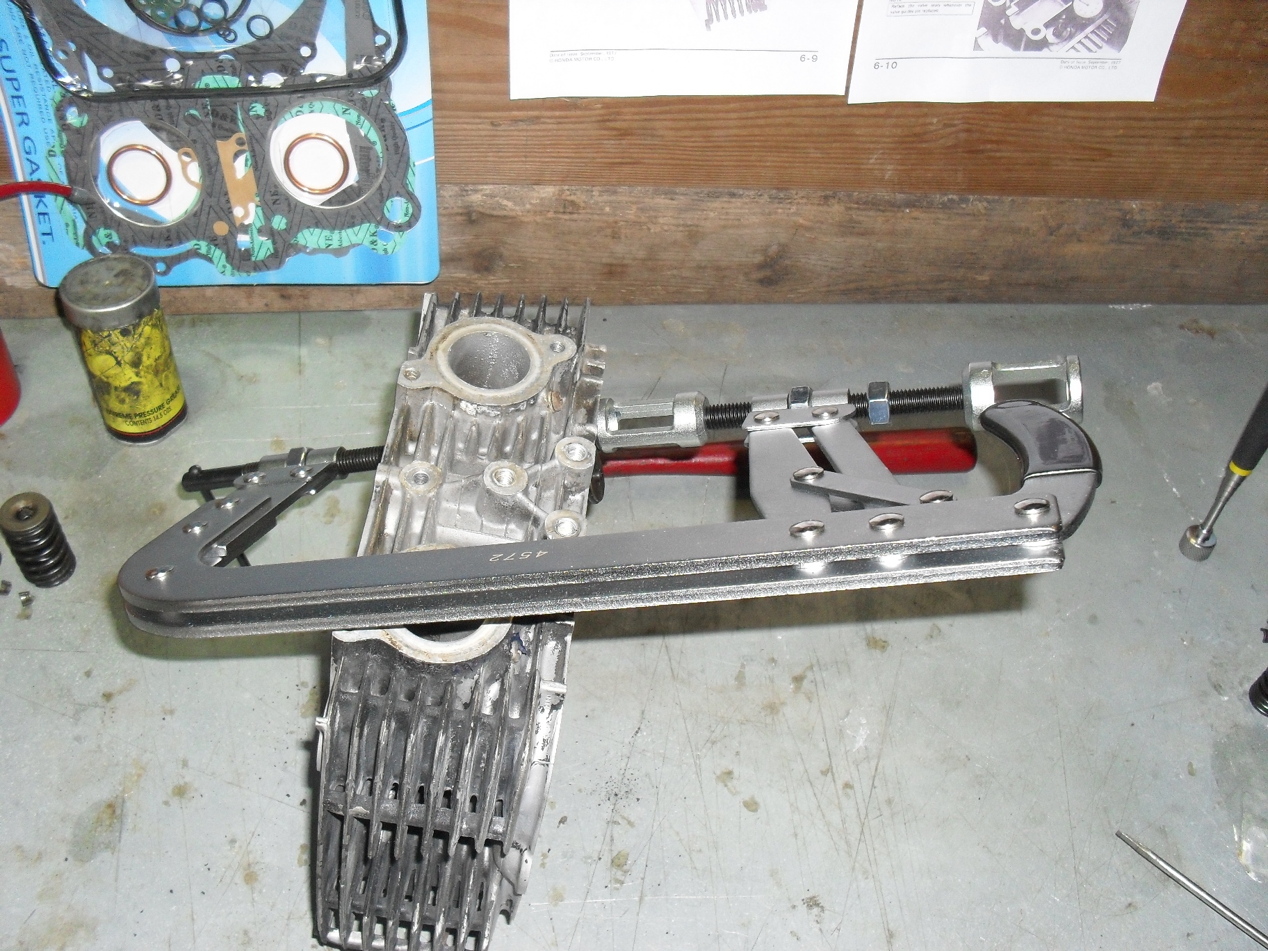
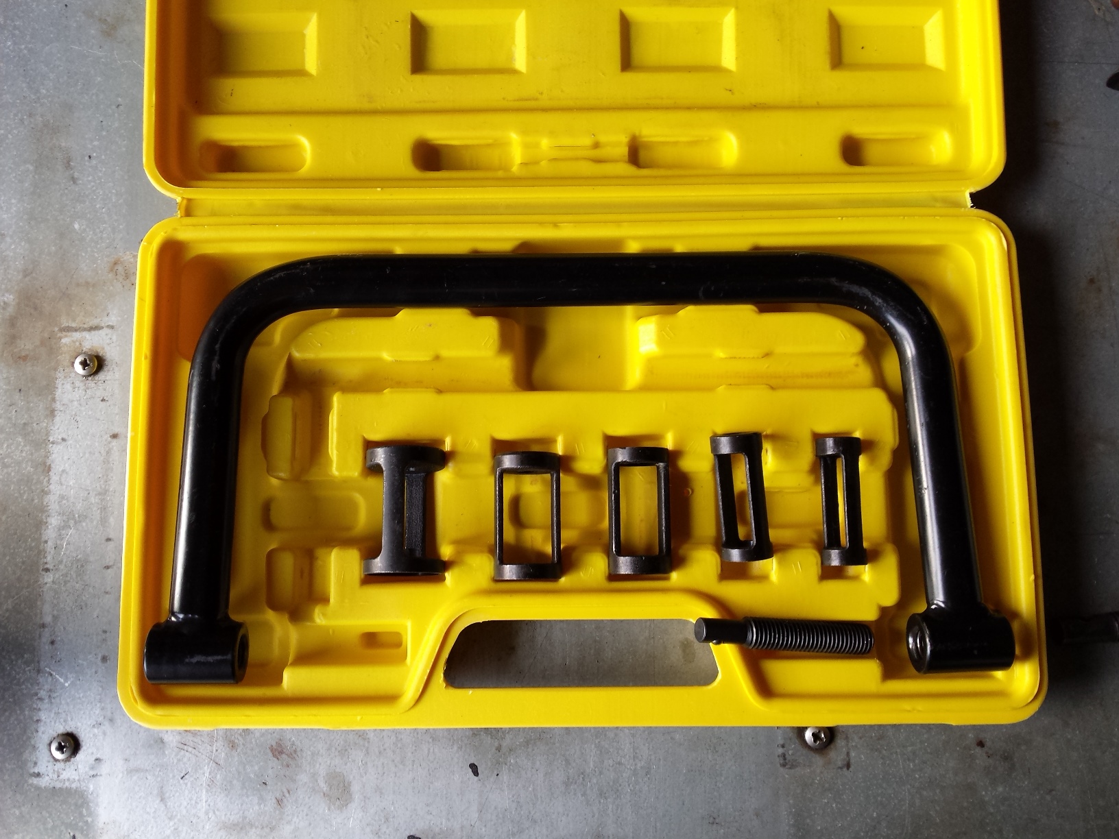
Enter the $46 OTC 4572 Large Valve Spring Compressor in it’s no frills cardboard box. Fancy blow molded plastic cases are nice, but really don’t make much difference if the tools inside don’t work. In this case the manufacturer decided to save money on the packaging and not the tool.
When I opened up the box there was a surprisingly heavy well made tool inside. It was very similar in style, metal thickness, and finish to the more expensive tools I have used in the past at various shops where I have worked. There were two other cost cutting measures one being that it only comes with two adapters for different size springs and that it only had a cup style tip for the clamping screw instead of including an interchangeable ball style tip, which actually works for better in most valve spring removal applications Below it is laid out with the rest of the tools that I normally use when it’s time to lap a set of valves.
Here is a shot of it in place ready to compress a valve spring. At this time I’d like to point out that you do NOT compress the valve springs by pushing on the large handle with the rubber hand grip. To get your initial setup pull the handle open to get the tool in place around the head and then push it closed. Then you adjust the adapter and the clamping screw until the tool is in the correct place. Then you turn the t-handle on the clamping screw to compress and release the springs. To move on to the next valve spring, first release the tension on the spring by retracting the clamping screw, and next you release the handle, move the tool to the next valve, close the handle, and once again use the clamping screw to compress the spring.
Repeat as needed until you have removed & reinstalled all of the valves as needed.
Below you can see a fully compressed valve spring with the valve keepers removed.
The bottom line? The OTC 4572 Large Valve Spring Compressor is worth the money. It may lack a full range of spring adapters and accessories, but if you don’t need all of those things this is a solid well made tool that will get the job done.
Today I’m going to show you how to perform a Honda CM400 valve adjustment. This basic procedure covers 1978-81 CM & CB400T Honda twins. This engine is from a 1980 CM400. Please refer to a proper CB/CM400 service manual to verify the exact procedures & specifications for your motorcycle. I will give the valve lash & misc. other tune up specs at the bottom of the page.
Gather up the tools you will need along with a copy of the appropriate service manual. Please note that it is not necessary to remove the engine from the motorcycle to perform this procedure, I already have this engine out so that I could do some some fabrication work & painting to the frame. This is the long delayed Project wAmmo bobber that I should have finished months ago, but now I am back on it with a vengeance. You will need to remove the fuel tank, gear shifter, and whatever other parts are necessary so that you can remove the valve cover & the left side crankcase cover. Once all of that is done then remove both sparkplugs.
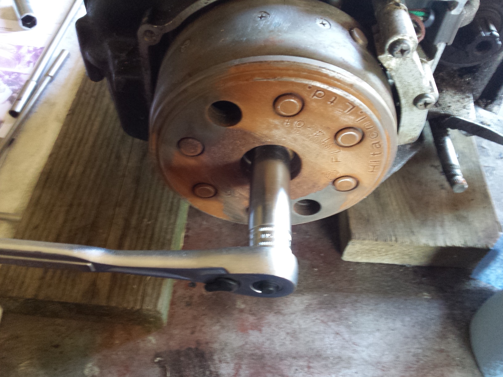
After you remove the spark plugs, switch sockets & turn the engine in the direction indicated by the arrow on the alternator rotor. The big rusty flywheel looking thingy you see in these pictures for those of you who have never seen one before. This one had to have some of the rust sanded off so that I could see the markings on it.
Turn the engine and watch for the intake valve rocker arm on the side you are adjusting to move down and then back up. These little Honda twins have a 3 valve per cylinder layout with 2 intake valves & 1 exhaust valve per cylinder.
Once the intake rocker arm returns to the top continue to turn the engine slowly and line up the next “T” mark on the flywheel with the pointer on the engine case, as it comes around. If the exhaust rocker arm starts to move you have gone to far & must circle the engine all the way back around & start over. Do not turn the engine backwards to get to the timing mark if you miss it.
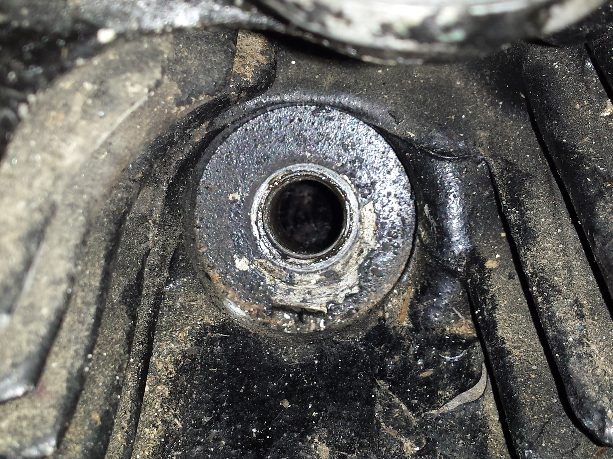
Then verify that the piston is indeed at top dead center. On this engine it is fairly easy to do just by looking into the spark plug hole.
With the piston at top dead center for the cylinder you are adjusting both the intake & exhaust valves should a little bit of play in them unless the engine has severe wear or improper maintenance that has caused valve recession which will close up the gap. Too much lash is also detrimental to your engines performance and will cause your engine to tap very loudly. Too little lash will eventually lead to a burned valve if it doesn’t close completely.
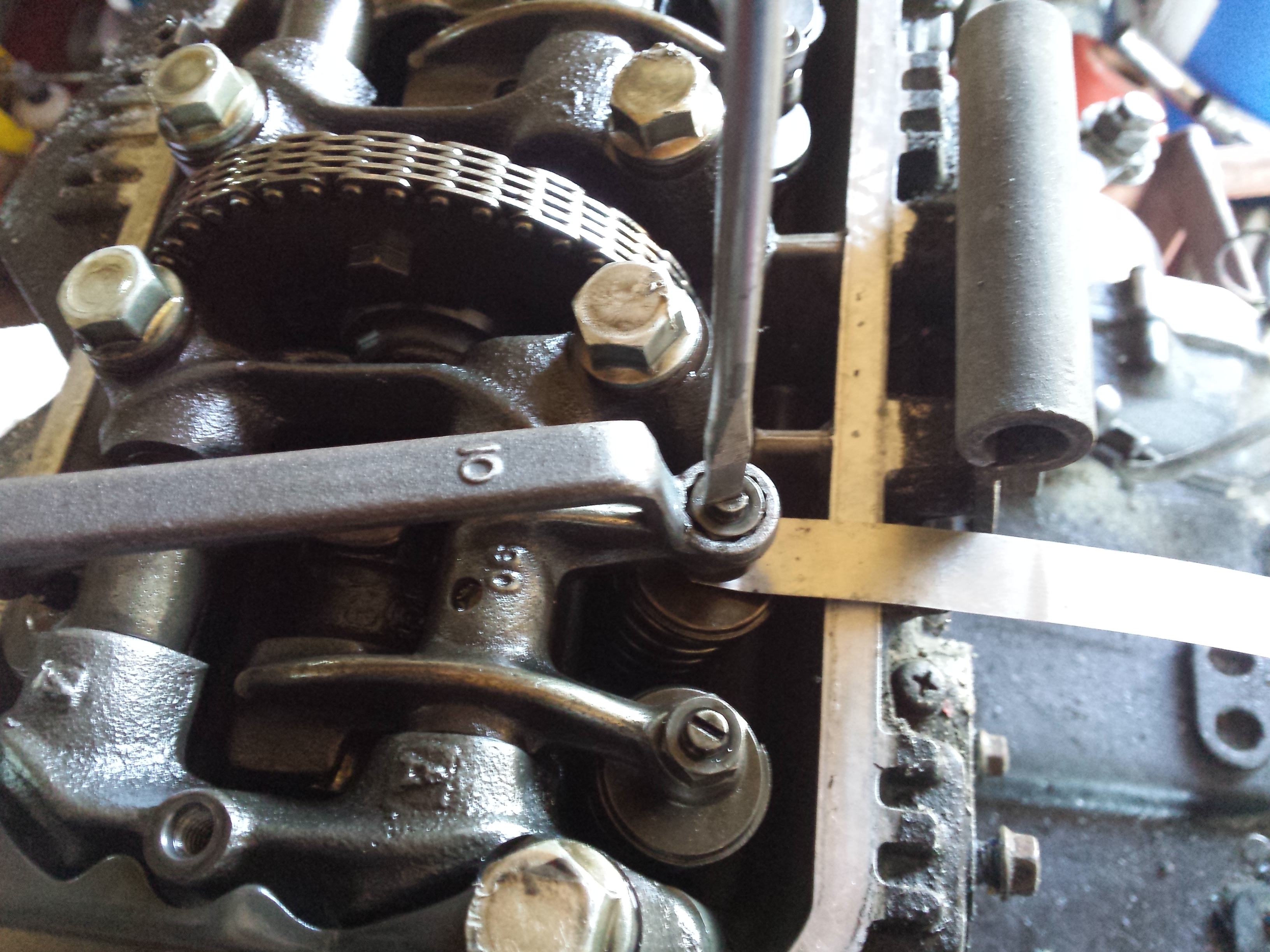
Loosen up the lock nut for whichever adjuster you choose to start with, here I am starting on the exhaust side.
Then insert the proper size feeler gauge, loosening the adjuster with a flat screwdriver if needed.
Then carefully tighten the adjuster screw & lock nut until the feeler gauge is able to be removed & re-inserted with just a little bit of drag, but the next size larger feeler gauge should not fit. It will be necessary to hold the adjuster screw with the screwdriver as shown below while you are tightening the lock nut. Be sure to recheck your lash after you tighten down the lock nut for good, sometimes you may have to readjust to compensate for the adjustment screw moving when you torque the lock nuts.
Once you have all of the valves adjusted properly replace the engine covers being sure to inspect & replace all gaskets & seals as needed.
Valve lash and some miscellaneous tune up specs are below: