Dry Coat Rust Preventative Review

All of us who work with metal have a common enemy, rust insidious and seemingly unstoppable it creeps into all the places we don’t want it to be, destroying our hard work, valuable treasures & expensive raw materials. About a month ago I did a review of Metal Rescue rust remover from Workshop Hero. The product worked very well & I have been  pleased with it.

One thing we all know by now is that once you get the rust off of a piece of steel is that afterwards you have to keep it off. If you have ever removed rust from steel using any chemical method you may be familiar with a phenomena known as flash rusting. This occurs when you remove your rust free part from the solution (or the electrolysis bath), rinse it off and then leave it to air dry, only to find out that in a very short period of time, often well less than a day, the entire surface is covered in rust again. While there are a few finishes that actually  require a flash rust coating to work such as POR-15 semi gloss black chassis paint  & some gun finishing techniques, most of the time this is not desirable. Freshly machined parts are prone to flash rusting as well. In the past I have always just tried to coat all such surfaces with oil or grease to preserve them, and while this works it is messy, expensive & makes handling a pain. So when the fine people at Workshop Hero offered me a sample to test and to write about in this Dry Coat rust preventative review I jumped at the chance.

<rusty metal by motopsyco>

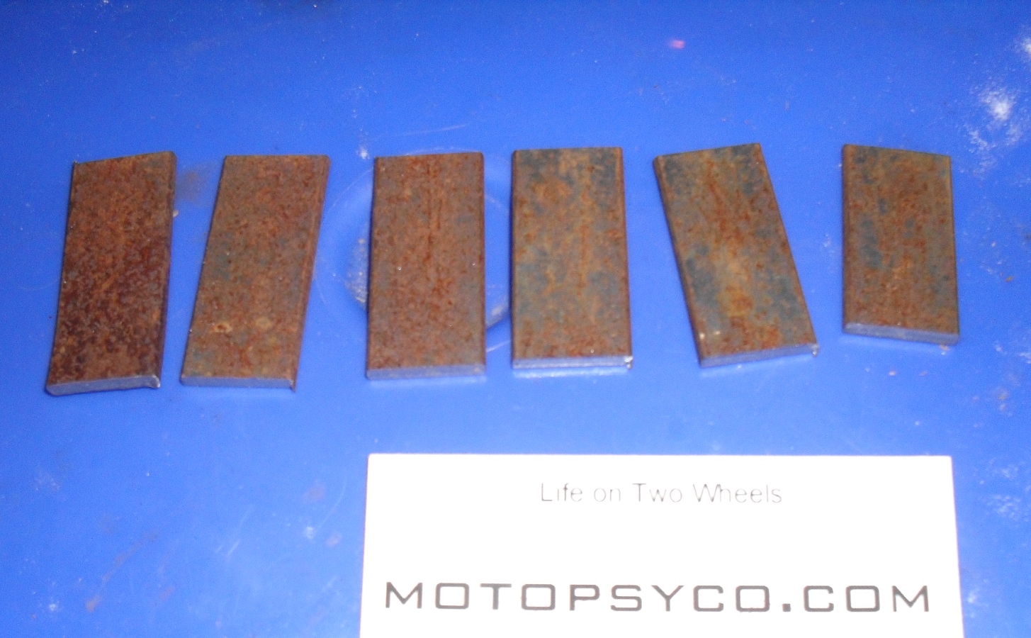
Just to keep thing honest & interesting let’s start by going out to the scrap pile and grab a rusty strip of 1/8″ thick x 1″ wide and cut six strips from it approximately 2 inches long. And then throw the strips into our bucket of Metal Rescue for an overnight soak. Yes this is the same solution that I used for the previous review, it has not been changed but it sure has removed a good bit of rust from various motorcycle parts.

<clean the rust off>

Compare this to the before picture the rust is gone, I rinsed the parts with water and patted them dry with a paper towel

<6 clean strips of steel Metal Rescue>

The plan for this little experiment is very simple to coat 3 of the strips with Dry Coat and allow to dry according to the instructions. Then I placed one coated test strip and one un-coated control strip paired together in 3 different locations around my property. This was on March 14th, 2015.

<metal recue dry coat rust prevenative review>

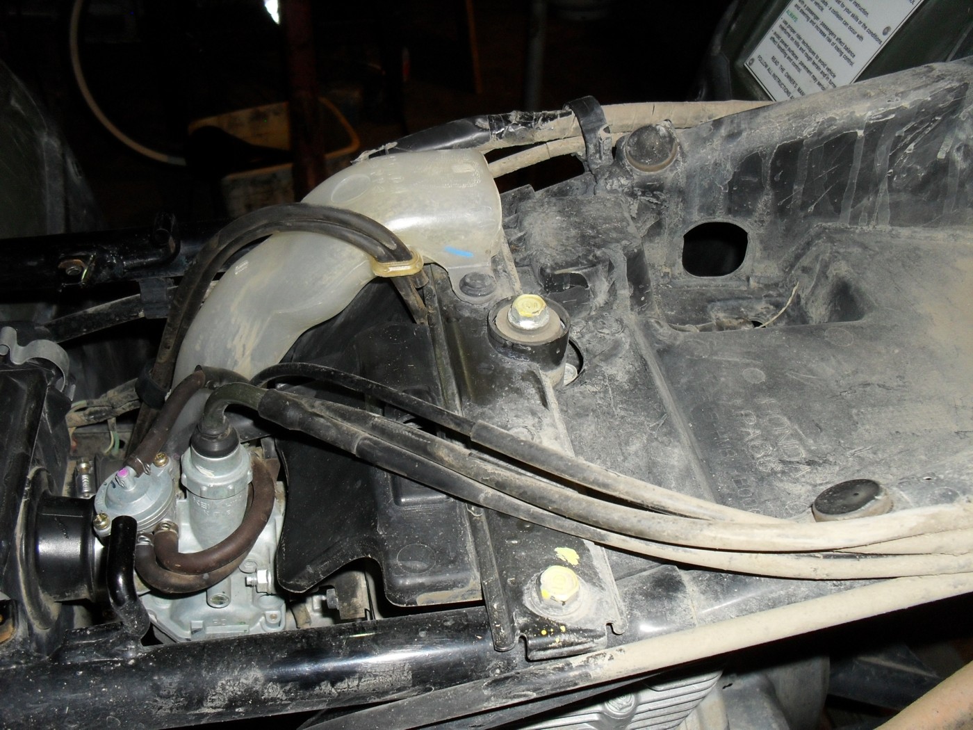
According to the company website it should give up to 2 years of protection from rust for steel parts stored indoors. The first two steel strips I left here in my office, literally indoors. The next two strips I placed on a ledge in the uninsulated, drafty humidity plagued old horse barn that I have converted into my workshop. Now this is definitely indoors out of the sun and the rain, but temperature swings cause enormous condensation problems that leave all of my bare steel tubing, rods, flat bar etc. coated in surface rust if they are not fabricated into useful items & painted quickly. If it can work here it should work at any other indoor location.

<out in a real workshop hero's workshop>

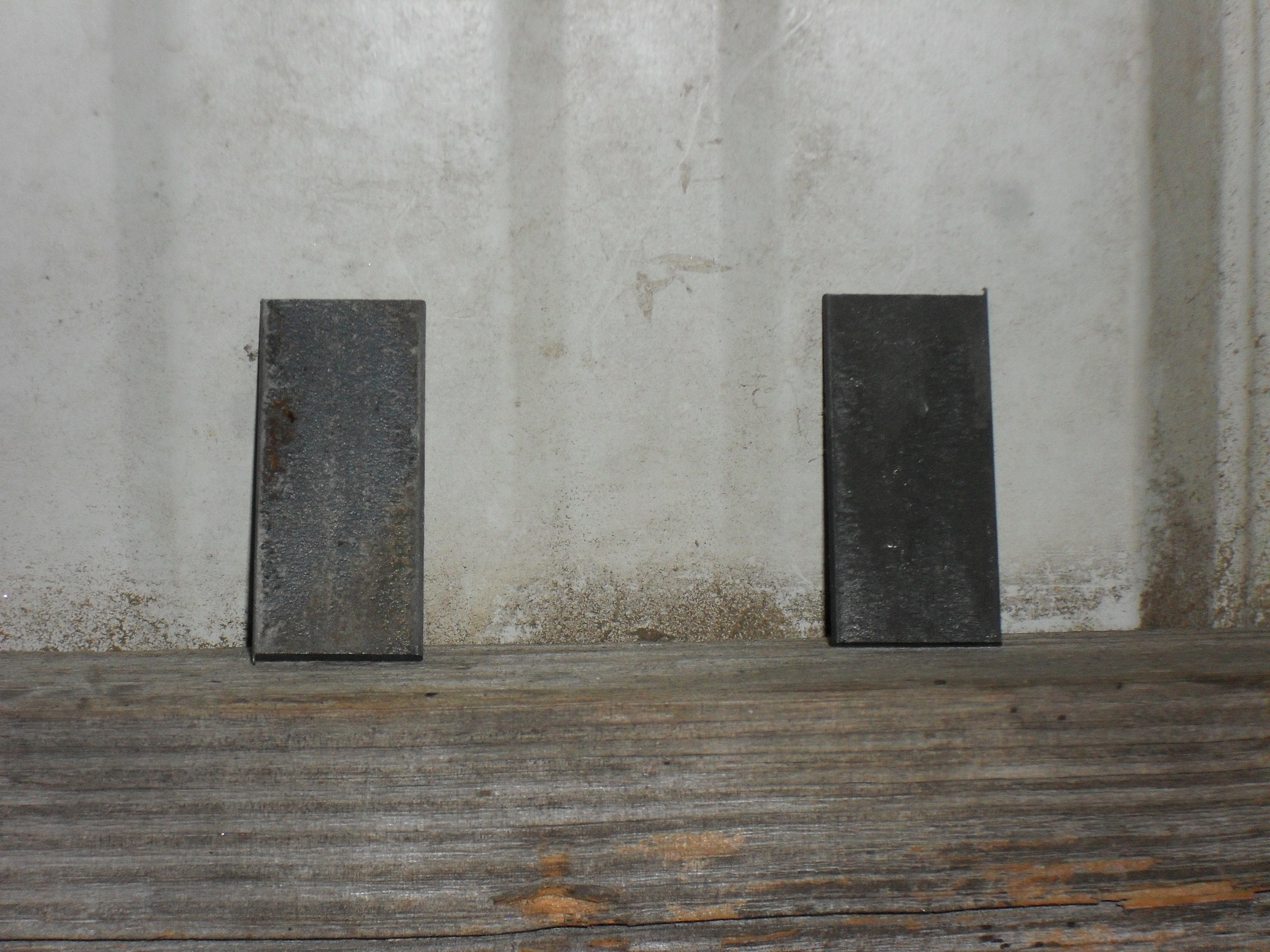
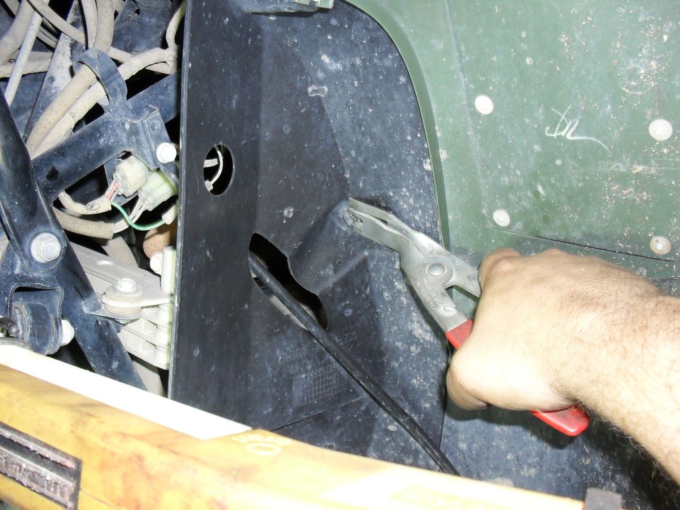
The final two pieces I stuck in a semi-exposed outdoors location. Let me be perfectly clear about one thing, this product is rated for indoor use by the manufacturer, if the coated strip rusts this is not a failure of the product, it’s just that an extremely curious cat wanted to push the limits. When I say semi-exposed, the two strips in the picture below are lying on the control enclosure of the solar panels that provide the lighting for my workshop. The solar panels are about 18 inches above them but they are exposed to the weather from 3 sides.

<dry coat test strips outside>

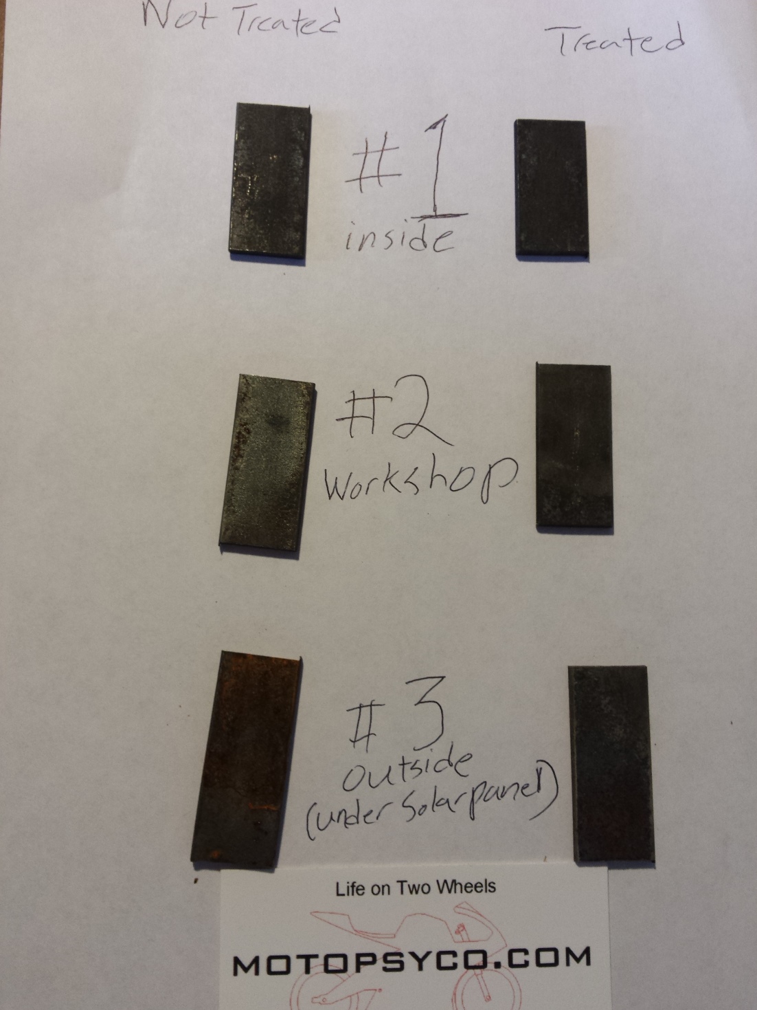
Just over 4 weeks later on April the 6th, 2015, I gathered all of the test strips together & photographed them. The parts that were coated with Dry Coat are on the right.

<workshop hero dry coat test>

I decided to flip the pieces over so you could see both sides.

<dry coat rust prevenative review>

Now lets look at some close up pictures. Here’s the samples that I left in my office. The part on the left is well on its’ way back to the original rusty appearance, but the part on the right is not. You can clearly see the pitting from the original rust before treatment, but not any new iron oxide formation.

<dry coat test sample 1 indoors>

This next sample is the one that I really wanted to check after a month in the old barn with a typical South Carolina late winter/early spring weather pattern. It is not unusual at this time of the year to have temperatures swing from 15-20 degrees Fahrenheit up to nearly 80 and then back down again in the space of a day or two. Of course when the frost melts in the morning it will sometimes look like rain inside of an uninsulated metal building. You can see the difference that this made when looking at the untreated part on the left, it’s a lot rustier than the control strip that was left in the house. Once again you can see that the coated strip is still rust free, even in the pits left behind by the previous rust that was removed at the beginning of this test.

<dry coat test sample 2 shop>

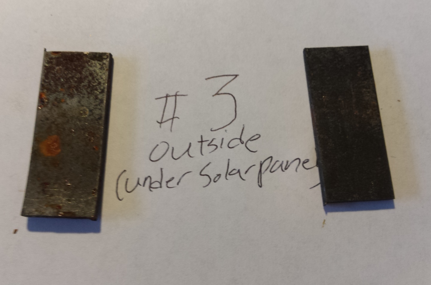
The outdoor test strips are next, the control strip on the left is quite rusty. The test strip on the right has developed a tiny bit of rust down in the existing pits in the metal. It still looks a lot better than the un-coated strip. Just remember Workshop Hero’s Dry coat is sold for indoor use and these last two test strips were just me satisfying my curiosity. The two pieces of steel shown here, have been rained on several times, and subjected to near daily freeze/thaw cycles. I am still pleased with the results and wouldn’t have problem recommending this product to anyone.

<dry coat test sample 3 outdoors>

I did download a copy of the Material Safety Data Sheet for this product so that I could see if there was anything in it that required any special protective equipment beyond the usual safety glasses and gloves. It is non toxic, non-flammable, and does not require any special disposal precautions. I didn’t see anything about welding two pieces of coated steel together so I contacted the manufacturer’s representative, and was told that they suggest washing any parts that are to be welded with soap and water first. The coating is 3 microns thick and probably wouldn’t interfere with most welding or cutting processes, but it would be wise to follow their guidelines.

So who needs this stuff? Obviously those of us who restore or repair old motorcycles, atvs, tractors & automobiles. Also machine shops, especially those of you who are storing & shipping items like re-bored steel cylinders, crankshafts, and other bare steel parts. Steel fabrication shops & o.e.m. manufactures of steel plant equipment, platforms, vehicle parts, or anyone else who stores bare steel either as a raw material or a finished product and needs an inexpensive solution for temporary prevention of rust, without having to deal with a hazardous material.

Both Metal Rescue and Dry Coat are available in a wide variety of sizes ranging from small bottles, 5 gallon buckets, 55 gallon drums and even 330 gallon totes for industrial users. As I said this is not permanent rust protection but it beats using expensive, messy, and hard to remove paints, oils and greases just to keep rust off of steel for a short period of time until you can use it.

Product recommended. I am going to place all of the test strips back in the places where I had them and will check on them over time. If anything changes I’ll be sure to let you know.

Another Project wAmmo CM400 Update

It’s time for another Project wAmmo CM400 update. Let’s start with my confession that I lost interest in the project for a little while and was really short on time for it. Had some issues with getting the frame sandblasted so I wound up bringing it back home and hit the frame with some paint remover and went over it with my little hand held sandblaster before coating it with spray on truck bed liner. Did the same thing for the tank before brazing up a couple of damaged spots on it and sealing it with Caswell Epoxy Gas Tank Sealer. I also wound up replacing the fork because I was unable to identify the one that was on it to get the proper repair parts so I replaced it, and installed a set of tapered roller steering head bearings for good measure.

<project wammo cm400 bobber>

I got the modified Harley solo seat covered in olive drab Cordura fabric to match the overall theme planned for the bike.

<olive drab solo seat>

Even though the engine would start and run okay, compression on the right cylinder was consistently 50 psi less than the left cylinder. Even after adjusting the valves (click here for the proper procedure) which didn’t help, and putting some oil in the cylinder to see if it would come back up temporarily indicating worn rings, the right side was still 50 psi lower than the left side so I went ahead and pulled the engine apart for a top end overhaul.

<CM400 Engine top end>

The problem turned out to be that the oil rings were frozen to the piston and the gaps were aligned on the top 2 rings preventing them from sealing. The downside to this bike originally being such an artistically created “natural” ratbike is that it was incredibly nasty. Here I am soda blasting the cylinder to clean it. Yes that is the cheap hand held sandblaster
and it works just fine with blasting soda, so if you’re on a budget & just need to clean a few small parts without damaging them the way sandblasting can try this. Just do not hit any gasket mating surfaces with the soda.

<soda blast motorcycle cylinder>

Once everything was cleaned & honed I taped off the mating surfaces so that I could spray on some Duplicolor cast iron gray engine paint.

<paint prep motorcycle cylinder>

<Honda CM400 clutch cover>

The original clutch cover will be replaced with this good used one and since I was not splitting the cases for a full overhaul I sealed up the bottom half of the engine with duct tape so that I could degrease it and remove the existing paint.

<aircraft peeler really works>

Since the head needed a good clean up, it became the subject of a head service tutorial that you can read by clicking here. The next picture is of the original pistons with new rings ready for the cylinder to be re-installed. The blocks of wood  held the pistons up and level while beautiful assistant slid the cylinder slowly into place while I compressed the rings.

<Honda CM400 pistons>

<freshly honed Honda cylinder>

This looks a lot better than the before picture doesn’t it? Once I got the head back on it was time to line up the timing marks for the crankshaft & camshaft as shown below and put the camshaft back in.

<Honda 400 timing marks>

<Honda 400 twin camshaft timing>

Afterwards it was just a matter of putting the rest of the parts back on and torquing everything down properly. Don’t forget to fill the oil pockets under the cam lobes with oil before putting the rocker box cover back on.

<cm400 bobber engine>

The engine is now ready to reinstall, I am going to leave the rotor cover off until later, ditto for the new clutch cover.

<wammo engine in frame>

Now the engine is sitting back in the frame. The intake spigots are new replacements for the damaged originals.

<I like puzzles>

I like puzzles

Now its time to sort out the wiring harness. Sometimes it is easier to start from scratch but for right now I am going to attempt to reuse at least some portions of the factory harness.

<honda twin regulator rectifier>

Normally on a custom motorcycle one would attempt to hide such parts as the regulator rectifier but since I am going for a post apocalyptic paramilitary look on this machine it is bolted to the side of the rear fender out in plain sight.

<Honda CV carbs>

Once I get the wiring sorted out and get the wheels back on it’ll be time top restore this set of CV carbs. I will probably do an in depth post on that process when the time comes.

Peace Y’all

Dirtbike Carburetor 101 Part Two!

Welcome back everyone,

At the end of the last class we ended with the carb sitting on the bench and the intake port in the head plugged to keep out dirt & small critters. Now let’s pull off the vent hoses and turn it upside down on the bench like this.

Take note of the pilot mixture adjustment screw that I have labeled here for you. I will be giving you a tip about it later in the lesson so be ready to refer back to this picture if you need to. Please remember these are not in the same place on all carburetors. I have seen them on the top and on the side depending upon the make and model. Some late model machines have them hidden under aluminum caps to keep you from tampering with them, but if you have a real problem you can remove the caps to repair it. Just be sure to replace them especially if you have to pass emissions inspections in your state. As usual I recommend you consult your handy dandy service manual for your motorcycle just to be on the safe side, because some carbs have more than one aluminum plug and you don’t want to remove the wrong one. Trust me I know….

Of course this bike has none of those annoying issues so let’s go ahead and take the screws out of the float bowl and look inside.

EWWW!

Now I am a fairly environmentally conscious guy, I grow organic veggies, the shop that I work in is powered by solar electricity, drive reasonably efficient vehicles etc. but you will never convince me in a million years that today’s gasoline is good for the environment. Once the lead was removed there really was not that much left to improve. There is no way  fuel that will rapidly break down into this toxic and corrosive sludge as fast as the fuel made in this day and time, can possibly be good for the environment. Just think of what it is doing to your vehicles as they sit in the driveway right now.

Let me get out of rant mode and get on with the lesson; here’s a shot of it with the float removed. You should be able to push the pin out to one side with a small punch and lift the float and float needle (float valve) out of the bottom of the carb.

So when someone tells you the float is sticking this is what they are talking about. Sticking floats are usually caused by either a piece of trash getting under the point of the float valve, or if the motor has been sitting by gasoline evaporating, and gluing it into place with a coat of gunk like you see here.

In this next shot I have removed the jets and the mixture adjustment screw. Even if you have a service manual handy, before removing the mixture screw, turn it all the way in slowly and count how many turns it takes to go all the way in. Write the number down somewhere, and then remove the screw along with the spring the washer and the o-ring that are in the hole under it.

You’ll probably have to dig for the o-ring using a piece of wire or a small pick like I did above.

At this point all of the metal parts are ready for a good long soak in the parts washer or carburetor cleaner until tomorrow. In fact the longer the better. Gather up some supplies.

If you have an air compressor and a parts washer you may not need the spray carb cleaner. If you don’t have a compressor it is mandatory even with a parts washer or a dip bucket of carburetor cleaner. For this bike I did pick up a carburetor overhaul kit. If your o-rings are all still in good shape and you can get all of your jets spotless you may not need it, but it is often difficult to clean the idle jet good enough to work again even with all of the right tools. If it’s my own bike, and I am broke that week, I might chance it, cause hey it’s part of the price I pay for this hobby. If it is your bike, you are getting new parts, because if it does not work, then I would be working on it for free and that would just piss me off. You would probably be upset at me too.

Here’s a teaser shot of everything laid out on the bench after cleaning, be sure to come back for the next lesson!

exploded view!

Click here to continue this lesson!

Let’s Split! (engine cases that is.)

Hello once again Ladies, Gentlemen and Russell,
When last I posted the engine was sitting on the bench with the top end and most of it’s accessories removed. The next thing I did was to remove one of the piston pin circlips and push the pin out far enough to remove the piston from the connecting rod.

If you don’t have an impact wrench available you should probably remove the alternator rotor before removing the top end. This is one job that really does require the factory special rotor puller. Fortunately they are not expensive and like the service manual worth every penny.

To remove the camshaft and timing chain first remove the camshaft bearing retainer and rotate the engine until the crankshaft is at top dead center and the timing marks on the cam sprocket and the crankcase line up. Now you can slide the camshaft out while working the cam chain off of the crankshaft. For the picture below I stuck the camshaft bearing retainer back into place after removing the camshaft so you could see how it fits.

Now it’s time to split the cases first remove all of the bolts and gently tap on the small projection around the cases and they should begin to come apart. If they do not easily come apart double to be sure that you have not missed any bolts like the one in this picture, that is inside of the engine where you might miss it.

With a TRX250 Recon engine I like to place it front side down on a workbench that allows me to place the protruding shafts through the bench so that it sits level. Then gently lift up on the rear case while tapping down on the transmission output shaft until it pops free. If you need to pry on the case to move it remember that you should never pry on any of the gasket sealing surfaces or around the cylinder hole. The outside of the engine mounting lugs is okay and there is on small place in between the lifter holes that can be used.
Just remember that if it requires any kind of force to remove something may be wrong and you should re-check everything before proceeding.

Here’s another shot of the transmission innards.

As you pull the pieces out of the transmission and lay them out on the bench like this be sure that you keep track of every single piece, all the washers bearings etc. and where they go in the assembly. I like to re-assemble them all back to their respective shafts as fast as possible. Keeping these parts in order is critical because just 1 misplaced or omitted washer can destroy the transmission and maybe the engine itself.

Here’s a picture of the failed gear so far I have only found one of the lugs that snapped off of it. The others probably drained out with the oil.

One last shot of the nearly empty crankcase, only the crankshaft and bearings remain.

Now I have to clean everything up good and order the required parts so it may be a week or two before you see this engine again.
If you really want to keep up with how this is going please be sure to subscribe to this page via the link on the upper right side of the page.
Peace Y’all

Recon 250 Into the Engine!

At the end of my last post about this the engine was sitting on the bench, so let’s pull it apart now. Start with the external accessories such as the starter motor, rope starter, etc.

On a full tear down like this I prefer to remove the clutches from the engine before removing the cylinder and head. That way there’s not any damage to the connecting rod or piston should I accidentally spin the crankshaft around too fast.

Of course the best way to remove the clutch nuts is with an impact wrench, but if you do not have one wedge something good and solid in the clutch gears to hold it still, and don’t forget the centrifugal clutch nut is reverse threaded.

You’ll need a steering wheel puller to get the centrifugal clutch out. It’s possible you could get lucky and break it loose with a rubber hammer, but I doubt it. Don’t try it because you can damage either the clutch, the crankshaft or both by hammering on the clutch.

Now you can see the timing and oil pump drive chain, along with the shifter meachnism in the front of the shifter drum.

After pulling all the little parts off the front making sure to not exactly where all of the thrust washers go, it’s now time to move up top and unbolt the rocker box.

Now set the pushrods off to one side and unbolt the head an pull it straight up to remove and then do the same thing with the cylinder

Here you can see me using the magnet to remove the lifters from their holes.

Next I popped the rear cover off after unbolting it. The magnets in the alternator will make it feel like it is sticking together so be careful.

In these lat 2 pics for the day you can see the alternator parts, the stator is in the top one and the rotor is in the bottom picture. Next time we’ll split the cases!


Peace Y’all

Honda Recon 250 pg.2

The next order of business is to dis-connect the negative cable from the battery as shown here.

Remember any time you are working with any vehicle with a negative ground system (which is practically everything) always dis-connect the negative battery cable first and re-connect it last when you are working on the electrics.
The next 2 pics will show how I use the door panel tool to remove the plastic retainers from the bodywork. First you wedge up the sliding pin in the center enough to get the forks of the tool started under it.

Afterwards you can slide the tool into place as shown and pull the clip right out.
Of course you can just use a couple of screwdrivers or a pair of wire cutters to remove the clips. Don’t forget to look for clips or screws in hidden places like this.

To get the fuel tank out you first need to remove the handle for the fuel switch.

Once you have the tank out be sure to note the position of the various vent hoses and take note of the routing. If you pinch them closed during re-assembly your four wheeler may not run correctly, or may stall going up hill.

Once all the plastic is off it’s time to get down to the nitty-gritty. Now remove the foot pegs. This will save you lots of needless foul language and bleeding. Plus on some models you can’t get the engine out with them in the way.

Remove the foot brake and shifter after you get the pegs off and then drain the oil so it won’t be sloshing out all over the place when you lift the engine. It’ll take some weight off too.

Do take a little time now to put some penetrating oil on all of the exhaust system nuts and bolt that you can reach and let them soak a few minutes.

Then remove the plastic covers from the sides of the engine and the muffler & header as well. While I was doing this the head of one of the screws stripped out so I got out my extractor set to remove it. Normally I am a fan of inexpensive tools especially for the hobbyist but there are 2 things that I recommend that you buy the absolute best in the world even if you have to save up for it. The first is a good set of screw extractors and the other is a Phillips screwdriver set.

85% of the time I don’t even have to use the extractor because the left handed drill bit will walk the broken screw right out.
Back to our engine now it’s time to remove the carburetor and then unhook all of the other cables going into the engine. Leave the throttle and choke cables attached to the carburetor unless you plan to remove it to work on it also,

Be sure to loosen the clamps over the drive shaft boot!
The last item to get to is the reverse lock out cable located at the bottom rear of the engine under this little metal cover.

Now unbolt the 2 motor mounts on either side, carefully remove the spacers and slide the engine forward and tilt it as need to make the frame look like this.

Finally here’s a shot of the engine sitting on the workbench waiting to be completely disassembled… starting tomorrow.
Peace Y’all