While I was in the process of moving I managed to break the end off of my old auxiliary fuel tank that had served me well for over 20 years. When I went looking for a replacement most of the top name brands were rather expensive starting at $45.99 and going up. At the other extreme were a bunch of smaller unknown brand ones from China or India with decent prices but some long shipping times & unknown quality. As a compromise I settled on this one sold by Pit Posse for 39.99 It came with a decent length of hose & a good quality brass shutoff valve. Let’s be honest here, all of these plastic auxiliary tanks cost more than what they are really worth but comparatively speaking this one is a good deal coming from a U.S. based company. The actual product is still made in China though. I’ve been using this one since June 8th 2018 and am very happy with it.
My setup for adjusting carburetors.
You might notice that in the picture above that I have my vacuum gauges and auxiliary fuel tank hanging from an I.V. pole. If you’re serious about doing carb work on motorcycles & four wheelers you need to get yourself an I.V. pole. It turns out that you can get one pretty dang cheap too, click here to see them starting as low as $23 with free shipping. Well worth every penny.
My sychronizer gauges actually come from Honda and were purchased from the inventory of a shop that went out of business. If you don’t have a set and are thinking of buying some do yourself a favor and get a set vacuum gauges, not the mercury sticks. Of course if you have the money you could go for a Carbtune Pro setup. If my gauges ever quit that’s the one I plan to get.
That’s all for today just thought I’d post a quickie product review and share a couple of tips that you might find useful. Until next time,
There are two things that are commonly found when working on old motorcycles, one is cadmium plated parts that are faded, rusted or discolored somehow, and the other is broken or cracked mounting tabs on plastic parts such as air boxes or side covers. Today we’ll learn how to do a reasonably good job of creating cheap fake cad plating with spray paint. Then we will tackle a minor repair of some ABS plastic parts. Most of the black plastic parts on motorcycles are ABS and on some such as early sport bikes such as EX250 or 500 Ninjas the bodywork is also.
Cheap Fake Cad Plating
Let’s start with this steering lock that goes on my 1982 Honda C70. In the picture it doesn’t look too terrible, but this was after washing it in the parts washer with a Scotchbrite pad to get rid of some light rust.
Once it was dry I taped off the key slot and sprayed on a couple of coats of adhesion promoter.
After giving the adhesion promoter about 8-10 minutes to dry I gave the part a couple of coats of metallic “chrome” paint. This paint doesn’t really look like chrome but it really is a very bright silver.
After allowing the chrome paint to dry thoroughly, take a can of the metallic “gold” spray paint and from 18-20 inches away lightly fog the gold paint over the chrome. Just do one or two light coats. the idea is to lightly tint the part with gold but not to completely cover up the chrome.
It’s really best to do this in a well lit place so that you can see when there’s enough gold on the part and stop spraying it.
Here you can see my cheap fake cad plating next to one of the well sheltered original cadmium plated brackets from this same motorcycle. Naturally if you plan on having a 100 point national show winning motorcycle, real cad plating is the only way to go, but for your average rider or local bike night hero this is a nice inexpensive way to get a clean authentic look to parts that should look cad plated.
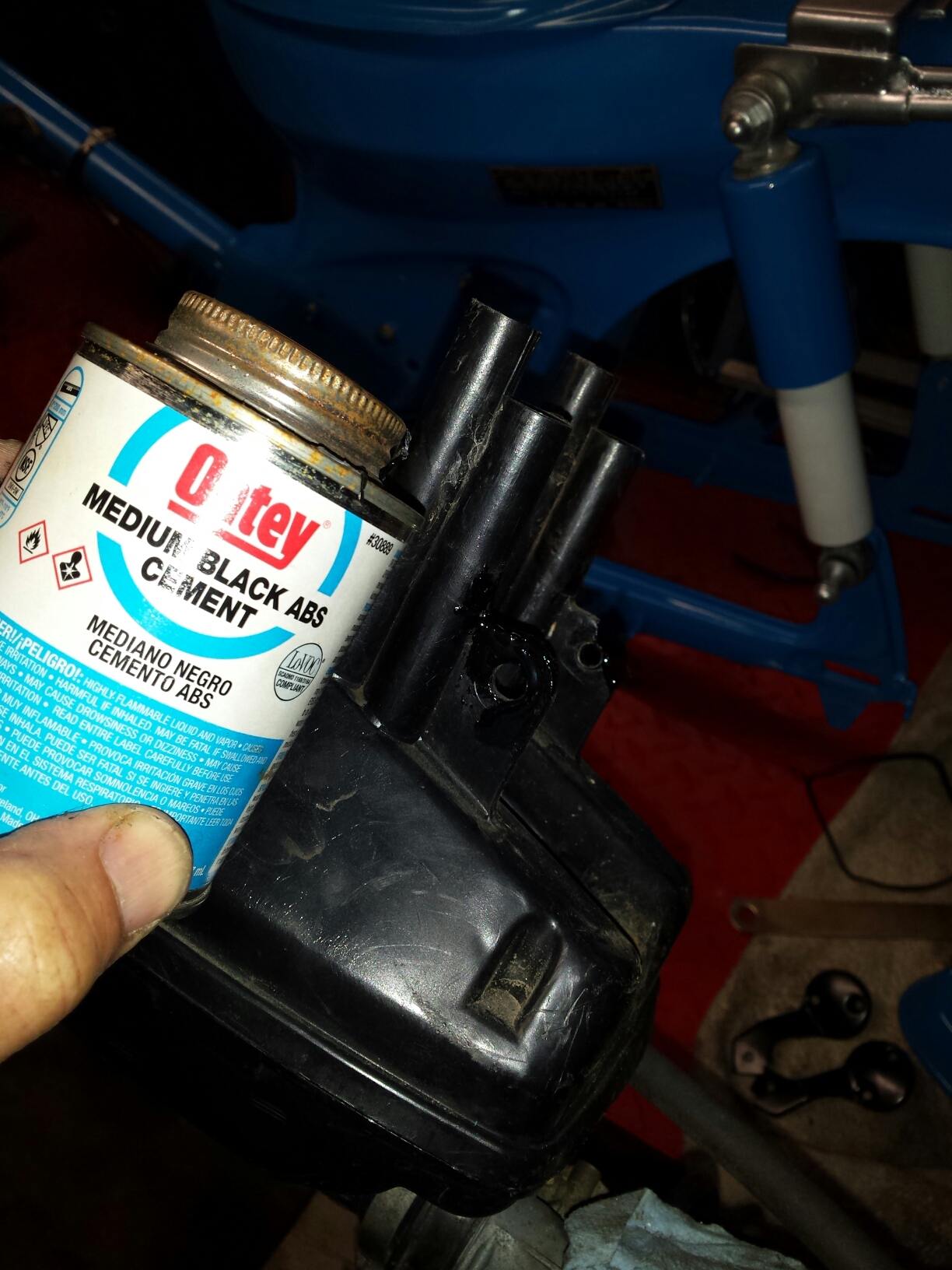
ABS Plastic Repair
A major source of aggravation are cracks in plastic parts and or mounting tabs broken off of them. But since since a lot of these plastic parts are made of the same ABS material as sewer & drain pipe there really is quite a simple solution. Glue them back together with common ABS cement that you can find at any local hardware store. The air box on this little C70 that I’m working on had been reinstalled at some point in the past without the metal spacers that are normally used to secure such parts to the metal frame without damaging it. The result was that one mounting tab was split & the other one was broken completely off.
To repair the cracked side was simple enough, it jut needed cleaning up and having plenty of glue applied. For the other side that was completely broken out I put a standoff with a washer in the hole & gave it a good coat of cement, permanently attaching it to the air box. You can also buy ABS plastic sheet & use that to fabricate repair patches, replacement tabs & even custom parts that can be glued together using ABS pipe cement. Once you are done & the glue is dry it can be filed, sanded or even painted over just like any normal plastic.
Hopefully these two tips about cheap fake cad plating & abs plastic repair will help someone out, until next time.
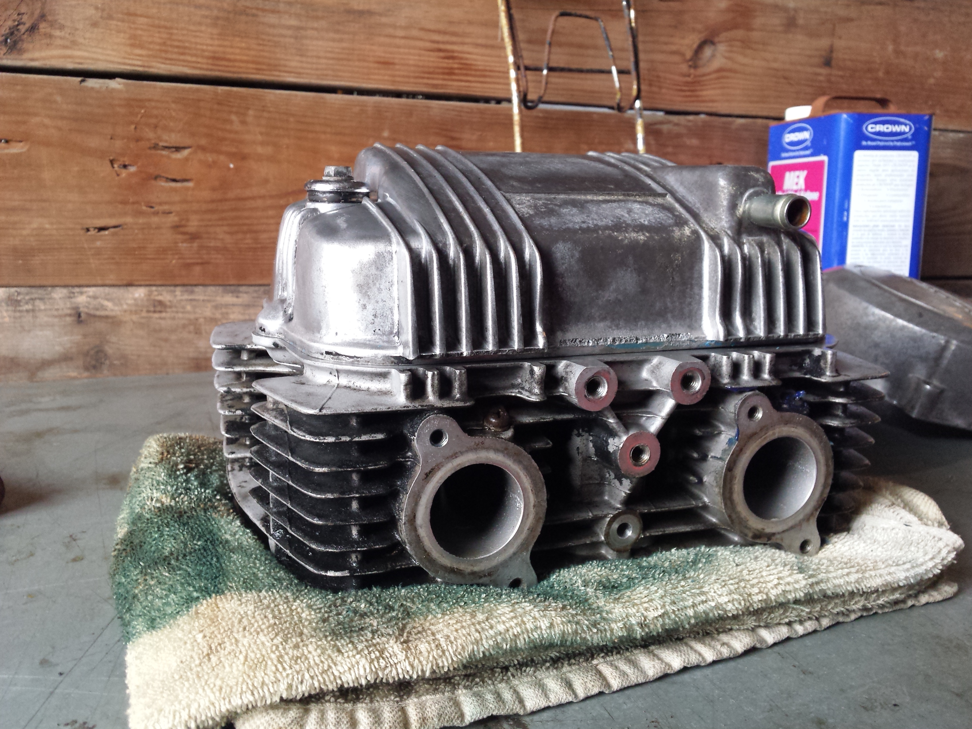
D.I.Y. motorcycle head service is possible for the home mechanic at times, under the right circumstances. Of course if you are one of those fortunate individuals who happens to have a fully equipped machine shop and know how to use it you can do anything. But for the ordinary person restoring an older motorcycle or atv that wants to save a buck or two it is still possible to do an acceptable job provided certain conditions are met.
My patient for this job will be the CM400 that I used for the valve adjustment tutorial a couple of weeks ago. After adjusting the valves and putting oil in the cylinders it still had about a 45-50 psi difference in compression from the left to right sides so I pulled it apart for a top end overhaul. It turns out that the right cylinder had oil rings that were stuck from sitting and that the gaps were aligned on the other two rings.
Before disassembling it, I cleaned the head fairly well and removed the carbon from the combustion chambers. This makes handling the parts much nicer and inspection much easier. No matter what method you use to remove the carbon do not allow any type of abrasive or wire brush or scraper to contact the flat sealing surface of the head. Yes I know you may have to use some type of scraper to remove the gasket residue from the head but be very careful not to scratch or gouge it in any way. I actually used soda blasting to clean this head but made sure not to hit the mating surfaces with it.
Now I must make a couple of quick disclaimers here. First there are some defects that if discovered during the inspection process that will mean you need to take your head to a machine shop to be repaired anyway. Second, unless you own a set ball micrometers to check them with, you will basically be guessing that the valve guides are okay based on the condition of the valve stems. Chances are that if like me, you are working on something old but with relatively low mileage they are okay BUT it is not guaranteed and excessively worn valve guides can cause oil consumption & smoking even with new seals. Third, this is not the high performance option, if you are building a hotrod and looking to squeeze every last drop of performance out of it you can then I suggest you contact a reputable high performance machine shop for a good 5 angle valve job and new valve guides. This is to get your old heap running as good as possible for the least amount of dough you can spend. The fourth and last disclaimer is to always put safety first in the shop. You will be dealing with strong springs under compression. There is a chance that a tool could slip releasing a spring to go flying out at high speed and hit you or to pinch your fingers between the spring & the tool. Only use a good quality valve spring compressor
in good condition, make sure you read the instructions that come with it, & wear some eye protection too.
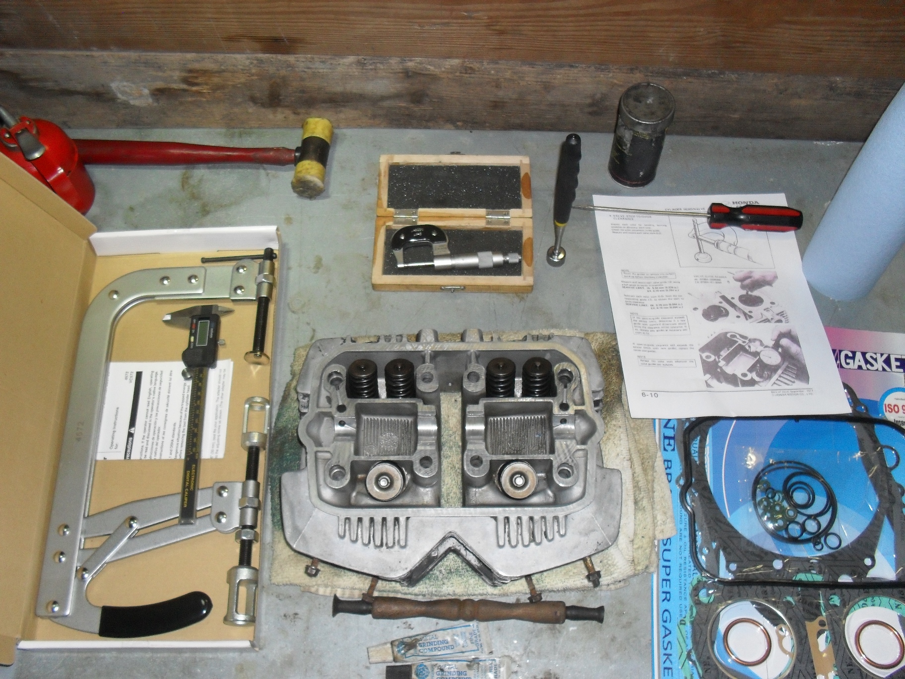
Even so there are some specialty tools you will need to get if you do not have them. In the picture above at the bottom center the thing with the two suction cups on it is a valve lapper with 2 tubes of grinding compound one coarse & one fine. Moving clockwise around the head are the valve spring compressor, a caliper dial or digital whatever you have, a light rubber or plastic hammer just in case something needs a tiny bit of extra persuasion, a micrometer (if you don’t know how to read a micrometer you can either learn how or just buy a digital one.) Next item to the right is a pick up magnet and a flat screwdriver, a few pertinent pages photocopied from the service manual and a new gasket set with valve seals. If you want to learn to use a micrometer watch the 2 videos below.
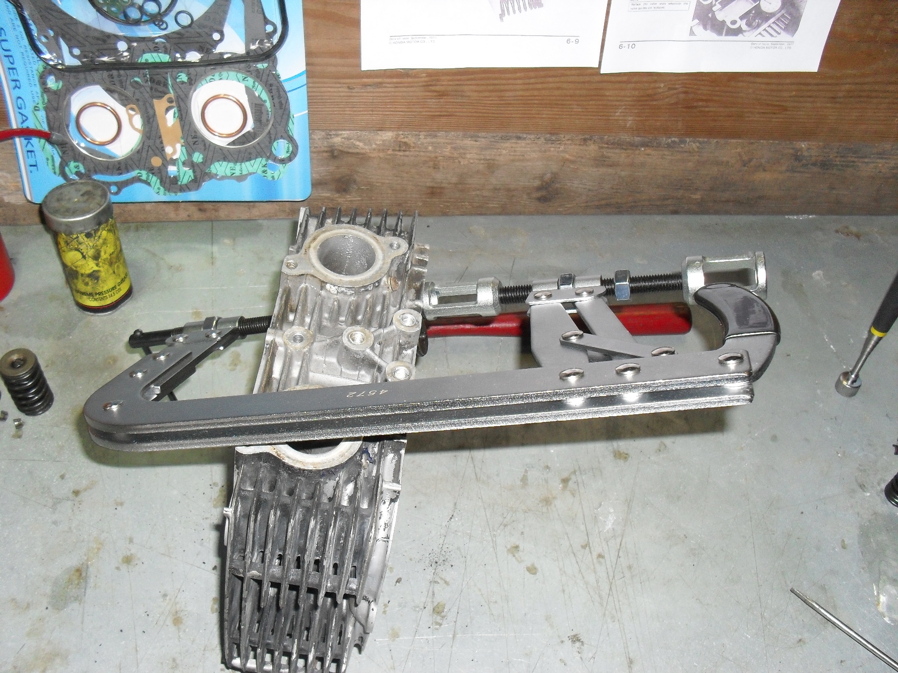
Set your valve spring compressor into place over the first valve you wish to remove and turn the compression screw inward until the spring is compress enough that the valve keepers either fall out or you can reach in with a magnetized screwdriver and pull them out.
It is very important that you keep your valves, springs, & other parts together so that they can be reinstalled in the same opening from which you removed them. This is especially critical for the valves as they wear into their valve guides and seats as the engine is operating. If any of the valves do not come out, or if removal is difficult you may have a bent or seized valve, put everything back together and find a good machinist. The cure for a damaged valve requires replacing the valve & seat as a unit. The valve guide drivers and reamers required for this job are really a bit much to purchase & learn to use for just one head.
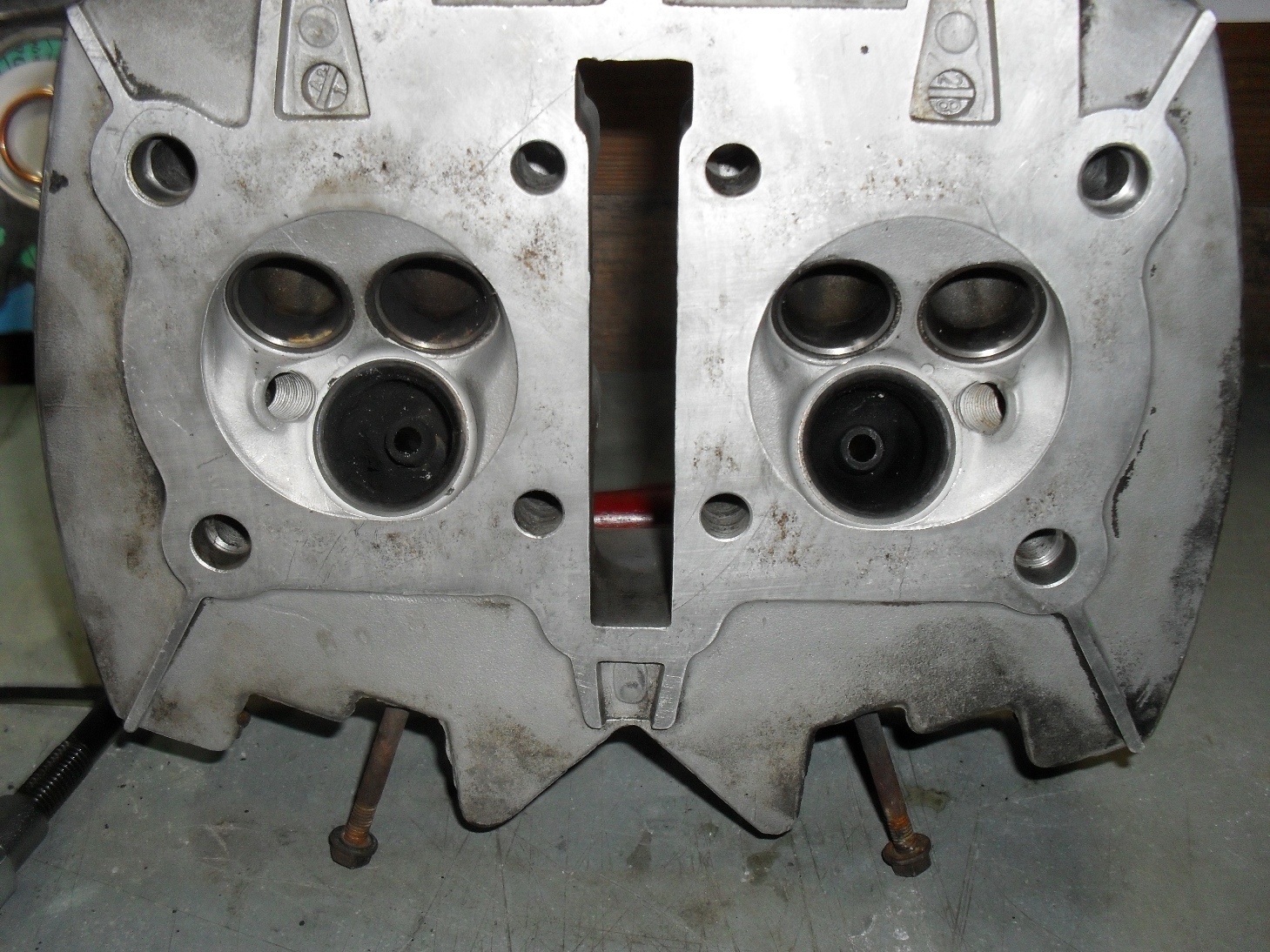
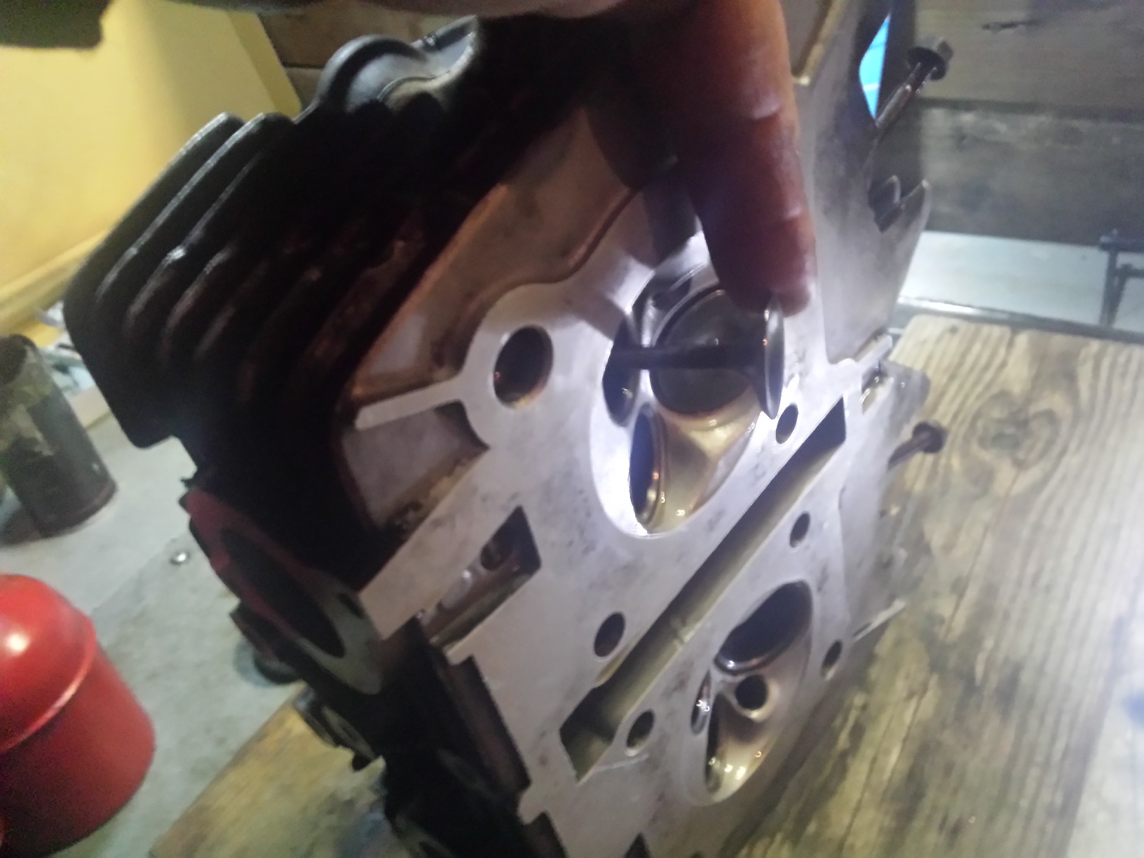
Once you get all the valves out give the head a good visual inspection looking for anything that looks galled, burnt, or cracked
Be sure you check inside the ports to especially around the valve guides. Next check the valve seats which are the hardened steel inserts around the outside of the large holes in the combustion chamber. If any of valve seats 0r guides are burnt, badly scored or pitted , have cracks in them or easily visible excess wear then you need to put it back together & take it to a competent machinist
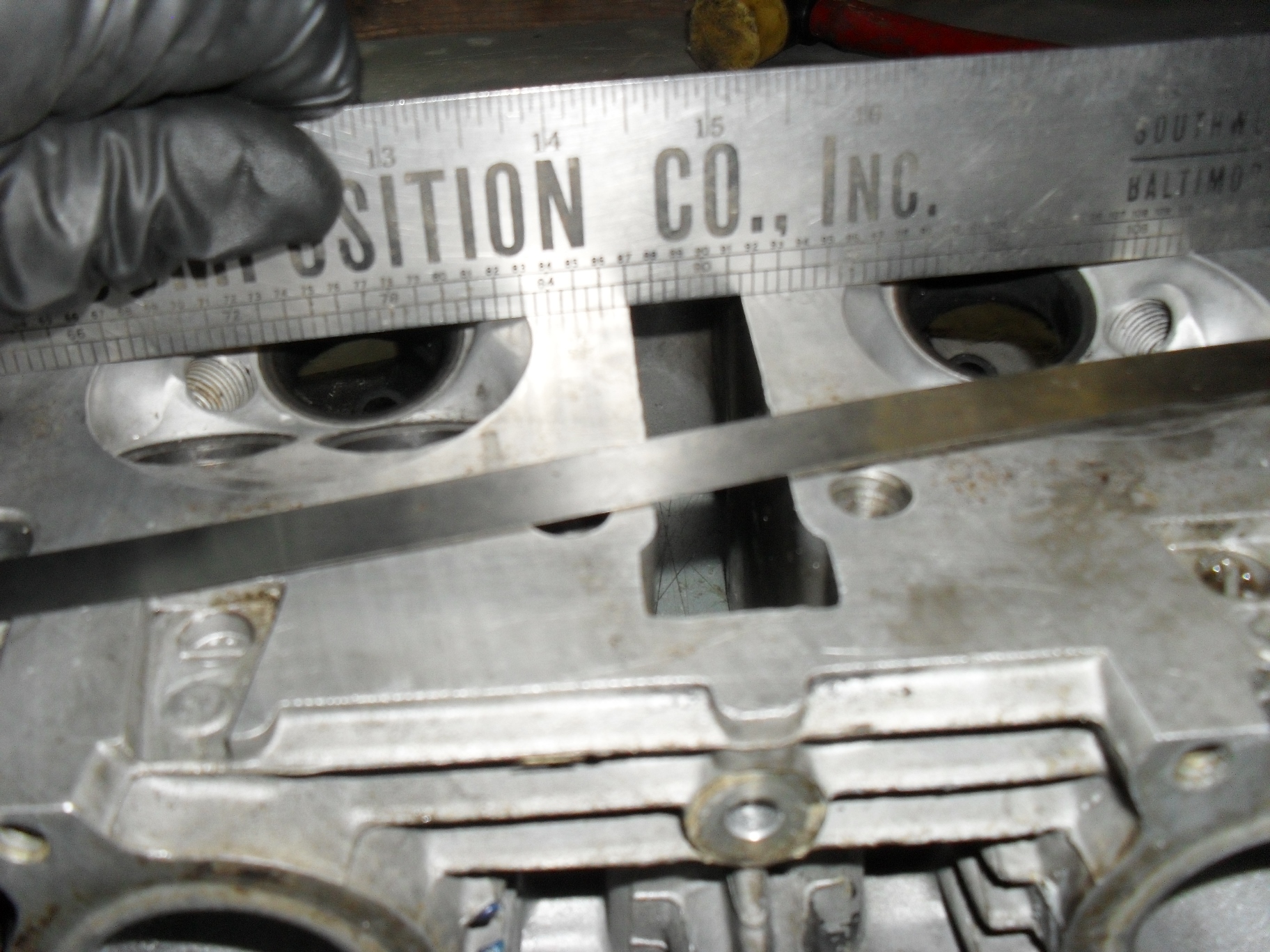
If all looks good make sure the head is not warped beyond acceptable limits. for this you’ll need a good straight edge and a feeler gauge in whatever size your service manual specifies
Place the straightedge firmly across the head in several locations and try to insert the feeler gauge between it and the heads gasket mating surface. If it goes between the two anywhere then a machinist will need to shave the head to level it back out.
Now it’s time to grab the micrometer and check the diameter of every valve stem in several places up & around each one. If any of them are worn beyond the service limit, chances are the valve guides are shot too and this is no longer a normal do it yourself job. Double check them for straightness at this time also,
After that get a caliper and measure the extended length of all of your valve springs. Replace any that do not fall into the specified range for your motorcycle.
Once the inspection process is complete and you are satisfied that all of your parts are in good condition & can be reused go ahead & clean the valves & guides thoroughly. Most of the time you can just scrub the intake valves clean in the parts washer, but the exhaust valves usually have a hardened scale stuck to them so I use a brass wire brush to clean them with. For the valve guides I use a gun cleaning brush, but any small round brush with plastic or brass bristles that fits through them will do. I try to avoid using brushes with steel or stainless steel bristles on parts like these because I only want to remove the grease, carbon, and scale without affecting the base metal.
Pick out whichever valve you want to start with and put a small amount of valve grinding compound around the head of the valve on the surface that contacts the valve seat in the head, and place that valve back into the hole that it was originally removed from. Grab the valve lapping tool & stick one of the suction cups on it to the valve like this and then rotate it back & forth to clean the mating surface. The most efficient way to do this is to hold the lapping stick between your palms and pretend you are trying to start a fire with it. Stop occasionally to check on your progress and replenish the lapping compound if needed. I use a coarse compound to start with & then switch to fine grit, but it is possible to make do with just the fine grit if that is what you have.
Stop and inspect rather frequently, you are not trying the grind the entire surface of the valve & seat flat. What you want is a uniform,well polished shiny ring all the way around the valve & seat at the point where the two meet. Once you have that, to keep polishing is just putting unnecessary wear on your engine parts. It should only take you a few minutes per valve to accomplish this, so keep going until you have all of the valves done.
With all of the valves lapped you now need to wash them and the head again and completely remove all of the valve grinding compound so that it doesn’t make its way into your freshly overhauled engine and grind up parts that don’t need it. Then open up your gasket set and find the valve seals. I have the seals for this engine laid out above.
The two larger one are for the exhaust valves and the four smaller ones are for the intake valves.
Once you have all of the seals into place it is time to start reinstalling the valves remembering to put each valve back into the hole that you removed it from to start with. First push the valve back into the hole.
It should go in smoothly, make sure that it doesn’t push the new seal off of the valve guide. Put the matching valve spring(s) and retainer back into place over the valve stem.
You will have to carefully hold the retainer while you put the valve spring compressor into place to compress the valve spring(s).
Compress the springs until you can see the grooves for the valve keepers well enough to reinstall the keepers.
Put a thick coat of grease on each retainer to stick it to the valve stem when you put it into place.
If at all possible use a pair of tweezers or needle nose pliers to put the keepers on the valve stem. If you find that you must use your fingers to get them both into place be extremely careful and make sure that the compressor is securely clamped and not going to suddenly pop loose and crush your fingers while you are positioning the keepers. You have been warned.
When you have the keepers in place on the valve stem then slowly unscrew the clamping screw and if necessary keep the springs and retainer straight as you release the pressure. Remember if your compressor has a release handle on it like mine does, do not use it to clamp & release the valve springs. Always use the clamp screw. The release handle is there to allow you to move it from one valve to another without having to fully unscrew the clamp every time. When you have fully released the pressure & moved the clamp your vale should look like the picture below with both keepers trapped securely between the retainer & the valve holding the whole lot securely together.
Repeat these steps until all of your valves are securely reinstalled in the head.
I have tried to be as honest as possible with you about the possible pitfalls and risks of D.I.Y. motorcycle head service, but if you are willing to take your time, check everything carefully, and work in a meticulous fashion there’s no reason that you cannot give it a shot. Just be willing to take the risk of trying on your next restoration or overhaul and you’ll find yourself having that much more satisfaction with your handiwork once the engine is up and running.
Of course since I want this one to look as good as it works I covered up all of the mating surfaces & plugged all the ports before spraying my favorite ceramic filled engine paint on it. If you need tools and supplies just visit my webstore’s tool sections and search for what you need. If you can’t find something there let me know & I will point you in the right direction even if it means sending you to someone else.
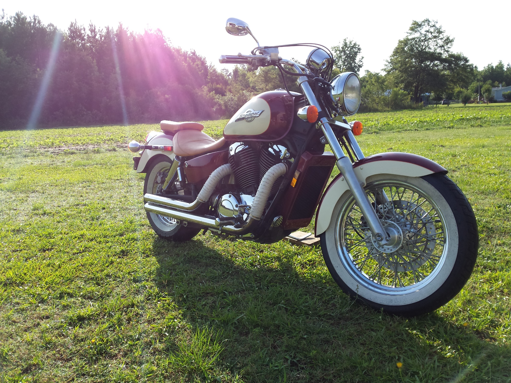
Let’s jump into another “how to” post! Above is today’s patient a 1997 Honda Shadow, a great riding 1100cc v-twin that while still running very well, needed a little tweaking. These motorcycles came from the factory with the carburetors set up toward the lean end of the spectrum for emissions reasons. This led to some drivability issues on some of them, when you combine the original lean jetting with a set of drag pipes, and 17 years of ethanol contamination it was running mighty lean indeed. The engine had a tendency to run hot, hesitate on acceleration, and frequent backfiring on deceleration. So I am going to pull the carbs off, clean them up a bit and install a Dynojet Research jet kit in them. To hear what this bike sounds like before the carb tuning click here go to my youtube channel.
First get the bolt out of the rear of the passenger seat.
Then remove the 2 from beneath the drivers seat one on either side
Lift it up and set it out of the way.
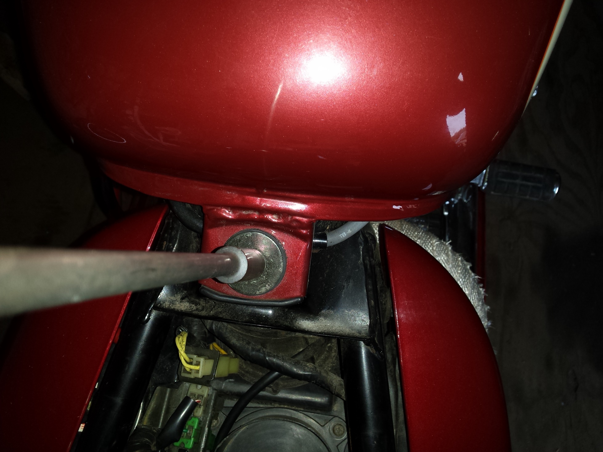
Locate the petcock and shut off the fuel.
Remove the bolt at the rear of the tank,
and the other one at the front of the tank.
Disconnect the fuel line from the petcock.
afterwards lift the tank high enough to remove this vent hose from the bottom
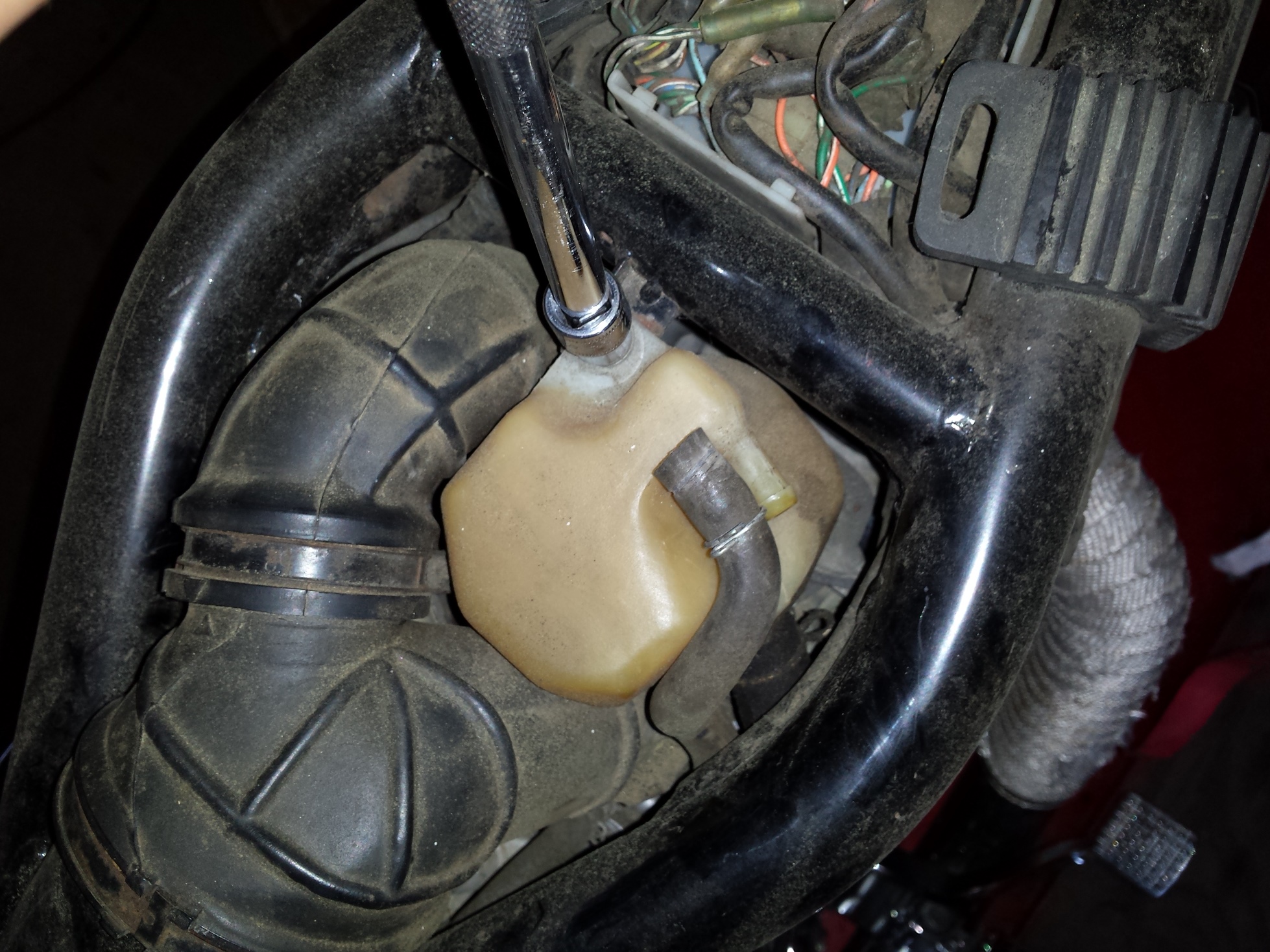
After you have removed the gas tank and placed it in a safe location this is what you should see.
The yellow plastic container is there to catch any oil that happens to emanate from the crankcase ventilation system, so unbolt it,
pull the hoses loose, and set it out of the way.
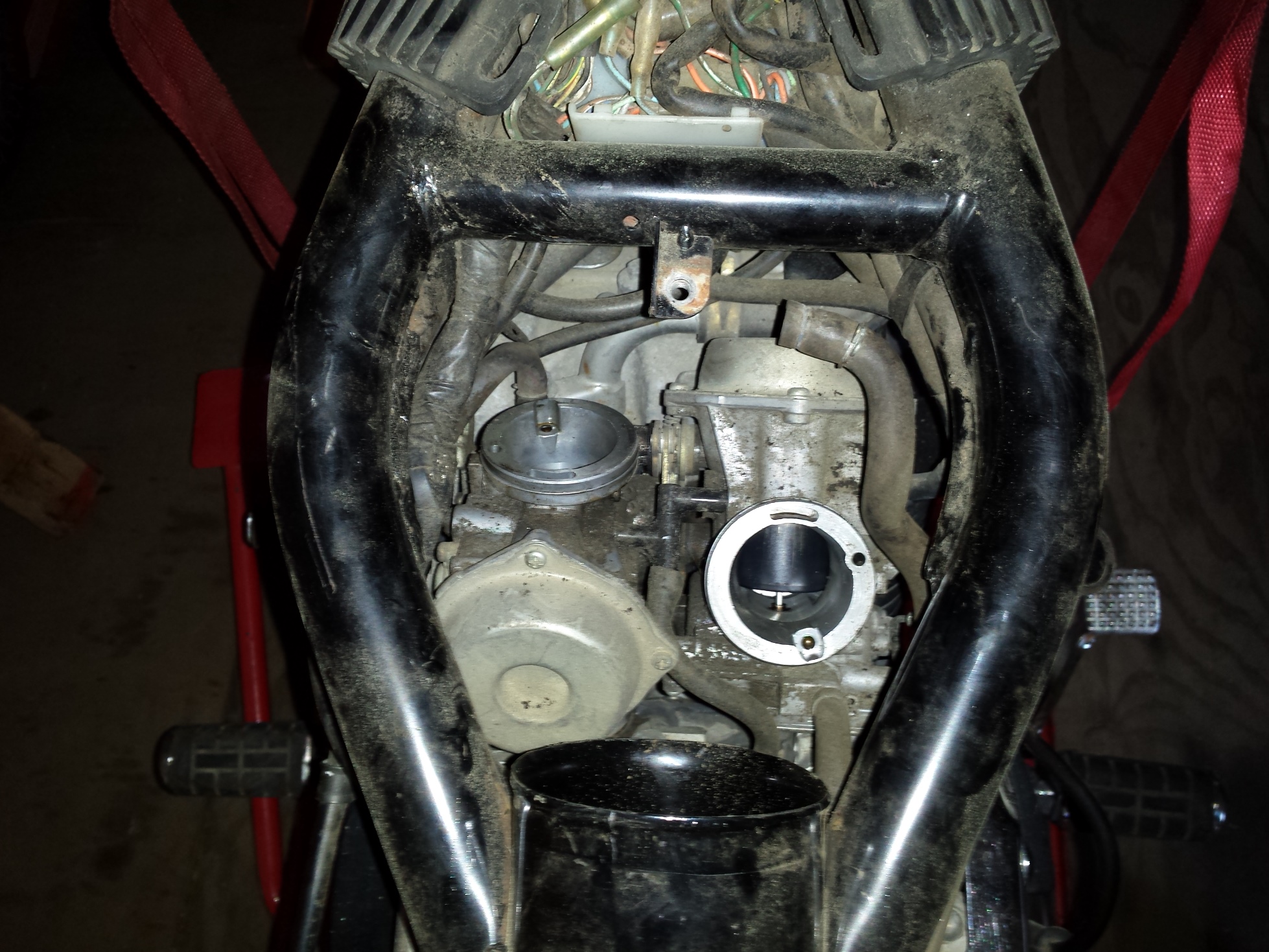
Next loosen the hose clamps on the rubber piping that leads from the frame to the inlet of the carburetors.
Now we can finally see the carbs!
Time to remove the throttle cables, remove the 2 screws (indicated by arrows) and you will be able to get the cables out of the pulley on the end of the butterfly shaft.
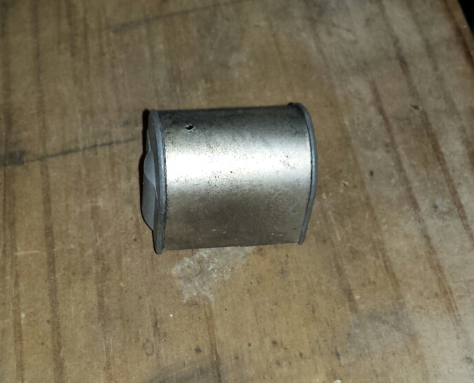
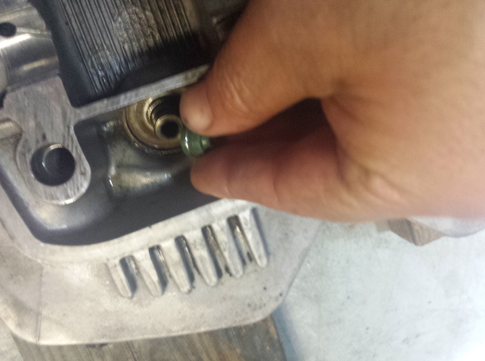
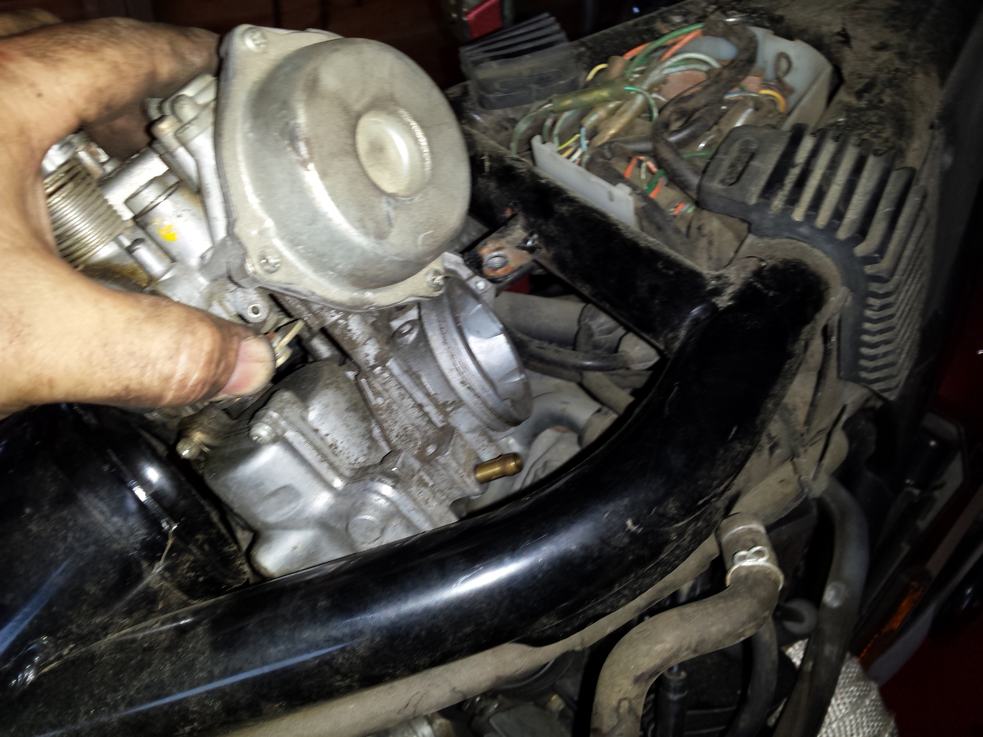
The cold start enrichener is next. These 2 little plungers take the place of choke flaps on the most of the last production carbureted motorcycles. Instead of blocking the air they just add more gas. It works well but is a bit more aggravating to remove. I used to have a special home made tool for getting these out but it has been at least 10 years since I saw it last so I just you whatever combination of open wrench & needle nose pliers that allows me to remove & reinstall them without boogering them up.
Here I am holding one of the enrichment plungers so you can see what it looks like on the inside.
Go around to the right side of the bike and pull the hoses in this tee junction that was connected to the crankcase vent reservoir and fold them back out of the way.
The rear spark plug wire runs through a loom that is attached to the right carburetor so remove it and the enrichener on this side.
You can reach under the carbs now & loosen the clamps holding the carbs to the spigots.
With a rocking and twisting motion you should be able to pop the carburetors loose, but dont rush to pull them up out of the frame just yet.
Before you try to pull them all the way out remove all of the fuel lines and vent hoses, being sure to note which hose goes to which barb.
These carbs come out of the top, just tilt them up sideways and turn them as needed, this is actually much easier than most Japanese cruisers of the same time period that require you to remove the carbs from the side.
Here are the carbs sitting on the workbench ready for cleaning. The next step is into the parts washer to get all of the exterior crud off for dis-assembly.
Keep checking back as I will be posting part 2 of this series very soon.
Here I’ve already removed the tank and all of the necessary engine covers.
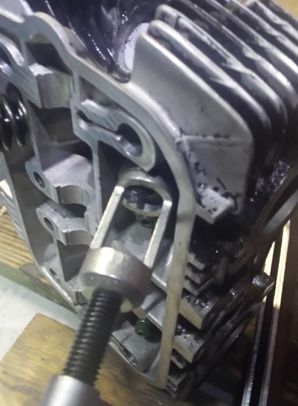
Since I have already put enough miles on this bike since I got it running to warrant an oil change I decided to re-check the valve adjustment for two reasons; one is that as long as the engine had been sitting without running I want to keep a close eye on it for a while & two so that I could show everyone how I do it. As you can see in the photo above I’ve already removed the gas tank, all four spark plugs and all of the appropriate engine covers. The first thing to do before you adjust the valve lash is to adjust the cam chain tensioner. On a 1980 Honda CB650 this is done by loosening the nut on the rear of the cylinder just a little bit. Do not remove it just loosen it some
This is the nut you loosen to adjust the cam chain tensioner.
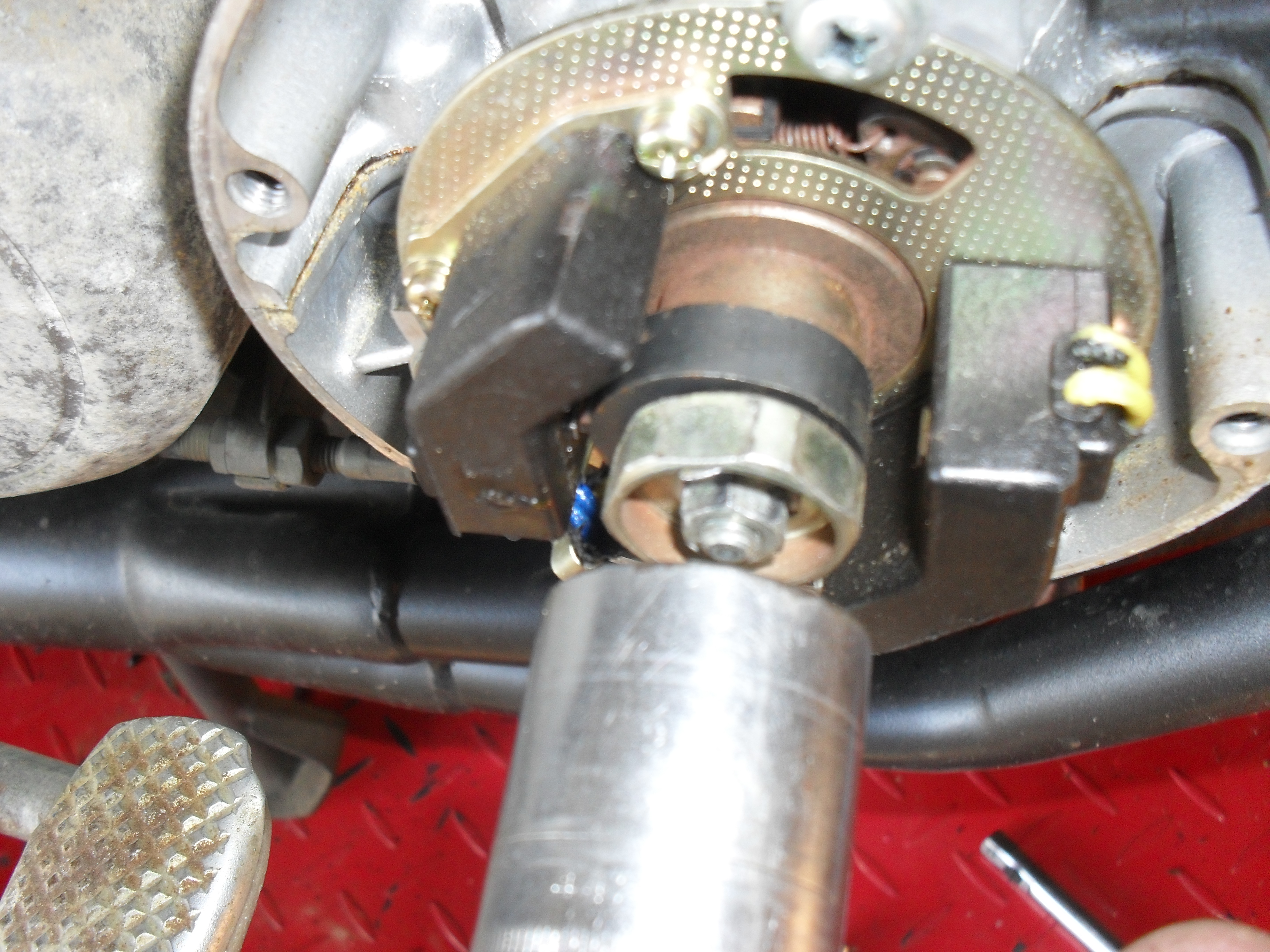
Then put the correct size wrench on the hex spacer behind the nut at the ignition unit on the right side of the engine. Then rotate the wrench clockwise slowly 4 to 5 turns as you simultaneously tighten the lock nut that you loosened at the beginning of this step. This is also the first thing you should try if you own a motorcycle and you can hear the cam chain rattling, but if after making the correct adjustments you still have a rattle then it will be time to start replacing parts. Keep the wrench that you used to turn the crankshaft handy, you are gonna need it a few more times.
The Clymer manual describes this as a 15/16″ nut. That is wrong this is a 24mm. OOPS
Here in this picture taken on the left side of the engine you can see 2 of the three openings in which we will be working to check & set the valve lash. The adjusters for the intake valves are on the back of the head in front of the carburetors and the exhaust valve adjusters are on the front of the head behind where the exhaust pipes stick out. The first step is to get the number 1 cylinder to top dead center. Take your large wrench and rotate the crankshaft clockwise and watch for the intake rocker arm on the first cylinder to drop down into the head and start to rise back up. Then look at the timing marks on the ignition advance unit (photo is further down the page) and continue to slowly turn the engine until the 1.4 T mark is aligned with the pointer that is cast into the crankcase.
The camshaft & rocker arms are in the left hole & one of the adjusters is in the right hole.
At this point both the intake & exhaust valve on cylinder number one should be loose enough both rocker arms to be wiggled. If not you either have a valve that is way too tight or you did not stop turning the crankshaft at the right mark, either way you should verify which problem you have before moving on. a simple way to see if the cylinder is at top dead center is to take a long small diameter wooden or plastic dowel and insert it into the spark plug hole. If the piston is at the top of the cylinder the dowel will not go in very far at all.
With the number one piston at TDC on a 1980 CB650 you should be able to adjust both valves on the number one cylinder, The exhaust valve on number two, & the intake valve on number three. Once you have those done you need to repeat the step above but this time watch the intake rocker of cylinder 4 on the right side of the motor cycle. With that one at TDC you can adjust both valves on number four, the exhaust valve on number three, and the intake valve of number two.
Lets talk about tools for a little bit. All of the shop manuals show a special tool for adjusting the valves, but the simple truth of the matter is that for a number of engines you don’t need them and this CB650 is one such example. For the lock nut, I just clamped a pair of Vise Grips around an old cheap 10mm socket that I have on hand and then just used the proper size of flat-head screwdriver to turn the adjustment screw with. Works great for me on this motorcycle, your mileage may vary, if you break something I’m not responsible, etc.
Macgyver was an amateur!
Speaking of tools let’s get the feeler gauges to set the valves with. The ones that I use are from Snapon and are about a foot long. The also came with a nifty holder that is very handy for working with the really thinner sizes in hard to reach places. The intake valve lash setting for this generation of Honda CB650 is .05mm (.002 inches) and the exhaust setting is .076mm (.003). So to do this job I will get out three feeler gauges in sizes .002,.003 & .004 (.1mm). Why three sizes? I’ll explain in a minute.
The next picture is of the .002 feeler gauge slipped in between the rocker arm & camshaft. This is where you measure the lash on this engine. Basically what I do is turn the adjustment screw until I can just slip the feeler gauge into place with just a little bit of wiggling. You should tighten the lock nut each time you do this as it may affect the final adjustment. If you tighten the lock nut and find that your lash setting has changed tighten the adjustment screw a bit to compensate, re-tighten the lock nut and check it again. Usually after I do all of this, and I am satisfied with my setting, I then take the next larger feeler gauge (.003) and try to insert it into the gap. If it doesn’t fit great I move on to the next one but if it slips in I readjust the lash until the correct sizes slips in fairly easy but the next size up wont go in. You may wonder why not just set it a little tight and not worry about it? I like to set these things exactly as needed for the best performance. The other reason is the way that motorcycle engine valves wear. Very rarely is there any wear at the top of the valve, most of the wear occurs where the valve closes at the valve seat in the head, this causes the valve lash to get tighter as the engine wears & not looser. This is especially problematic when you are running old motorcycles on the toxic, corrosive, & environmentally unsound corn juice that passes for gasoline in this day & time. If you must err on the side of caution it would be a little tiny bit better for your valve lash to be just a hair too loose than to be to tight.
For really thin feeler gauges like this .002 I recommend a holder like this one from Snapon tools.
Next take the .003 feeler gauge & set the exhaust valves as shown here. Then use the .004 gauge to make sure your adjustment is just right. It is especially critical not to over tighten the exhaust valve lash. If the valve wears down and is not able to close all the way due to a lack of clearance you may get a burned valve & a big repair bill.
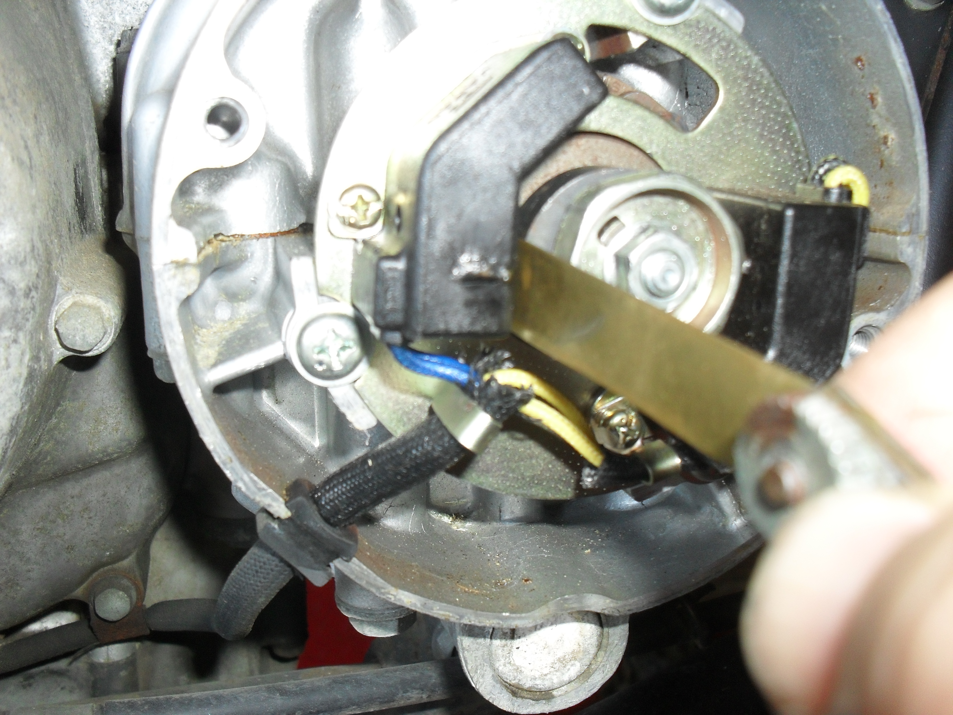
If you have a late 70s or early 80s Honda with the factory electronic ignition you definitely want to perform this next step. First get yourself a set of nonmagnetic feeler gauges. DO NOT not use steel feeler gauges to set the magnetic pickups aka pulse generators on these bikes.
Non-magnetic feeler gauges are a necessity to set air gap on the pulse generator of most OEM electronic ignitions of this time period.
The range of settings for the air gap between the pulse generators (black boxes in the picture below) and the trigger mounted on the end of the crankshaft is .012-.016 inches (0.3-0.4mm) You can also see the pointer & the timing marks that I mentioned above in this picture.
Believe it or not I have never seen any motorcycles with this gap set correctly from the factory, but the system is still good enough so that most bikes run without any problems whatsoever. Still if you have one of these and it runs okay except for a little surging & hesitation the pulse generator air gap should be the first thing you check. To set mine I just rotate the engine until the trigger ( little square nib sticking out of the crankshaft ) is aligned with nib on the pickup, loosen up the adjustment screws, stick the feeler gauge in place, & hold it all together while tightening the screws back down. Then rotate & repeat to do the other one.
This makes a huge difference in engine performance if it is set correctly.
There you have it, put a little lube on the advance mechanism behind the plate, reinstall all of your covers, spark plugs & fuel tank. Now it’s time to fire it up & check it out. Once you are sure that you did everything correctly & your engine is sounding just the way it should take it out for a ride & enjoy the fruits of your labor!
Today’s post is about those annoying rubber boots that attach your carburetors to the spigots on the head(s).
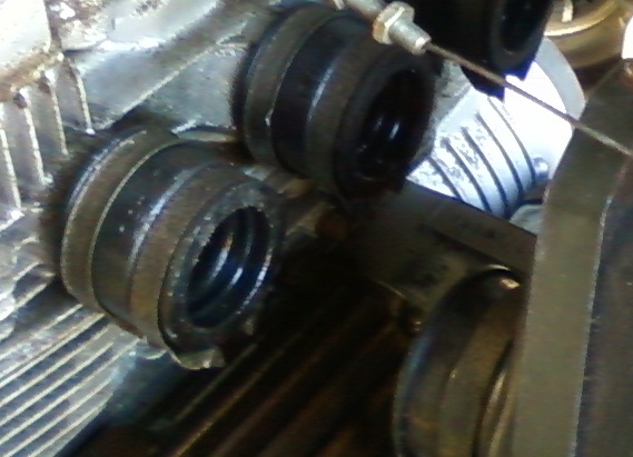
dry brittle old carb boots
Often on old project bikes these are hardened and brittle, most of the time you can get the carbs out but it is almost impossible to get them back in. One thing that greatly helps is to take a heat gun and heat them up to soften them. Some people on the net have removed them and placed them in very hot water. Regardless of the method a small amount heat will help get them soft enough to reinstall the carbs. Just do not use an open flame or you will end up with a charred & useless mess. On some motorcycles these bolt to the head and on others they clamp to spigots cast into the head. If you are dealing with removal of old intake boots from a set of spigots like shown in the picture above prepare to be very patient. Don’t just grab a big screwdriver & start prying! First loosen & completely remove all of the clamps, then twist and pull them by hand until they will at least wiggle & turn on the spigots. If they still won’t come off you have to decide if it is worth the risk to pry them off. Choose your leverage points very carefully, if you have any doubt at all about being able to remove them safely or if you are working on a rare or valuable antique or classic machine this is where you break out a good sharp utility knife & cut them off. The cooling fins and other castings on most motorcycles are very thin and will often break before an old piece of dry rotted rubber will,so better to be safe than sorry.
intake manifold clamps
Also be sure to look at the clamps when removing the boots. They are not just straight rubber hoses, often one end is bigger than the other, and the clamps are 2 different sizes as on this Honda CB650. The intake manifolds only fit one way but they have directional arrows on them, the clamps are not marked so be sure you note which ones go where.
That’s all for tonight, until next time have a fantastic life!
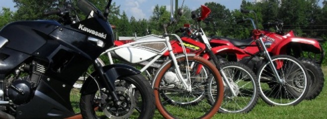
Here I’m just going to let you follow along as I remove the fairings, fuel tank, and exhaust system from my 93 Kawasaki 250 Ninja. Although the title of this blog is Life on Two Wheels, the truth of the matter is that for last year & over half of this year a true story of my life would have been called life in hotel rooms and rental cars. While I was away I still managed to squeeze in some bicycling time, and I did try on the occasional weekend to take my motorcycle out for a spin but unfortunately never far or often enough, and it has developed some problems related to long term storage anyway. A couple of months ago I started a new job, moved back home and now am ready to get back down to the business of serious recreational motorcycling again.
’93 Ninja 250 Fresh out of the shop after restoration 4 years ago!
This bike still starts right up and once warmed up will zip from idle to redline with just a flick of the wrist, riding it at low speed or for a short distance no symptoms are discernible. If driven at highway speed for more than 3 or 4 miles it begins to spit and sputter and stops like it has run out of gas. So far I have done all of the easy and obvious things such as verify the gas cap & other fuel tank vents, made sure the fuel petcock was working, and that both the in tank and external fuel filters were clean. So now its time to pull the carbs back off and check everything out. Since I am tired of having to pull the exhaust system off every time I want to change the oil filter (and it got some holes in it now also), I am going to pull the Yoshimura 2 into 1 header and replace it with a pair of Emgo Dunstall replicas using some custom fabricated adapters welded to the end of some factory head pipes.
As you are following along please be aware that my cycle is not stock. It has a few aftermarket, modified or bespoke parts on it so even if you have the same make and model of motorcycle you may notice many substantial differences between mine and yours. Just remember modifications to your motorcycle are made at your own risk, some may be dangerous or illegal in some places, I am not a motorcycle engineer, nor do I play one on t.v. Use your best judgement,consult your doctor, shrink, & attorney, then get a permission slip from your mom before imitating any mods you see on this site, because I am only responsible for my own stupidity, not yours. Now that the disclaimers are out of the way , let’s get to work!
First pull the mirrors.
Ninja 250 mirror removal
Unbolt the lower fairing I like to start with the front center bolt first.
Ninja 250 lower fairing remove bolt
Additional screws indicated by arrows.
Time to get the upper fairing loose You will notice some very blotchy spots in the next photo. It is not paint damage. I discovered the hard way that if you are shall we say a larger boy, you should not take pictures of shiny very reflective surfaces while wearing nothing but a pair of shorts. The resulting images were distorted,and bizarrely pornographic looking, so I blotched them out.
There is an arrow pointing to some damage to the tank that is a direct result of the hygroscopic nature of this damn corn syrup that the government is forcing into our gasoline. I’ll fix it, line the tank and paint it again.
Ninja 250 upper fairing screws
Then unplug the turn signals.
Ninja250 turn signal wires
You could have taken the seat off as the first step but I’m doing it now, just turn the key and pop it loose.
Ninja 250 seat lock
The side covers have one screw each at the bottom as shown here.
After removing this the side cover should snap off, pull it loose from the front first.
Here it is with the side covers off
Ready to remove the tank now!
Remove the bolts
Ninja EX250 fuel tank bolts
and then disconnect the fuel & vacuum lines from the petcock
Ninja EX250 fuel petcock
Hey look! it is a naked Ninja, enjoy the view.
Now you know what a sportbike looks like with no clothes
I still have to loosen the radiator to remove the head pipes. The hoses can stay attached but all of the bolts indicated by the arrows have to be removed from both sides.
NInja 250 radiator & fairing brace
This will allow me to pull it forward to remove the exhaust system. It’s hard to see in this picture but after unbolting the flanges from the head remove the bolts attaching the pipes to the frame. This particular system is suspended from the drivers foot peg.
My soon to be former exhaust.
It is crazy but all of the preceding steps were necessary every time I wanted to change the oil filter, I loved the sound and performance of this system but due to the extra maintenance work and the damage it has suffered over the years (it was on the bike when my wife bought it for me) I decided to replace it.
Yes I know they are mainly a scooter dealer. Even so all of you hairy chested macho badass guys & gals who only care about “real” motorcycles need to check these folks out after all in addition to the top quality scooters they also carry Cleveland Cyclwerks, Hyosung, and Sym motorcycles. Plus scooters are cool again, sure a lot of them are still 50cc post DUI transport, but there are available in larger fullsize and full speed models but in today’s world scooters are once again in style. And Carolina Fun Machines is the best scooter dealership I have ever had the pleasure of visiting. They are not some fly by night scooter dealer at the flea market, not a used car lot, with a batch of cheap shit scooters to sell for a quick buck but an actual functioning dealership that carries reasonably priced products of better quality. Plus the story of this stores founding is worth reading even if you have no other interest in their products, go check out the “about page” right now. Now click here to see the service department!
Here’s a shot of the store front for you.
Hey Look its a Misfit, some cool scoots, and a go kart!
For you crotch rocket jockeys, how about a Hyosung GT-R? You can get it in a 250 or a 650!!
Hyosung GT R sitting in the showroom.
Meet the Syms!
The 110cc Symba and the Cafe Styled 150cc Wolf Classic
There you have it folks they are a scooter dealer and so much more. I want to extend my thanks and gratitude to Tim and his staff for their help during my visit and for allowing me to drive the Misfit that I rode for my review last month. Please go visit the Carolina Fun Machines website or even better visit the store in person. Trust me if you live anywhere in North or South Carolina and are even remotely thinking of buying a moped, scooter of any size, or a small to midsize motorcycle, you owe it to yourself to check them out.
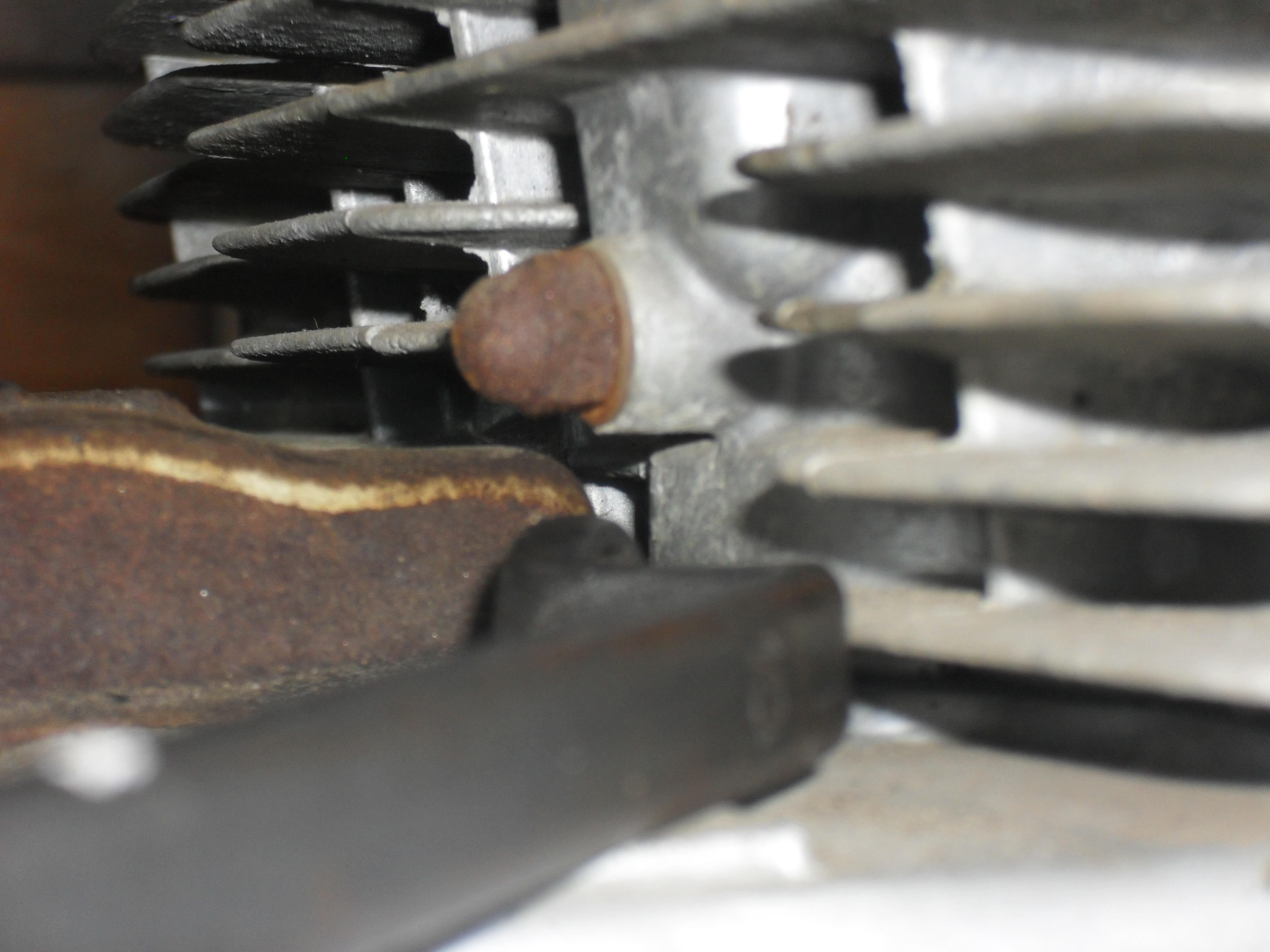
This tech tip is for all of the people who are just starting to wrench on their own motorcycles, although I have met a few old timers who may not know it. All of the big four makers do this on most of their machines. I don’t know about HD or the current European brands but all of the top Japanese motorcycle companies do it. They put punch marks on the various components that mount to shafts with splines. Shift lever, decompression levers, drum brake levers etc. almost always have punch marks indicating the correct alignment of the part to the shaft. Here is an example below from a Honda drum brake.
So now you know one more thing to look for when you start to tear into your own machine, and should your atv or motorcycle not have punch marks like this you can always add them before taking it apart if you need to. After all anything that makes it easier to reassemble your parts and get your machine running in top form is a great thing.
I’ve been wanting one of these for a long time. For years I used a wooden table or a chain hoist to lift motorcycles up for repairs when I just could not bear to get down on the floor to work on them. As I’ve gotten older the combination of a weaker back and a fatter wallet has made this purchase a lot easier to justify. So when the September issue of my favorite motorcycle magazine arrived on my Kindle with a coupon to purchase this lift for $299 I bought a print copy ASAP & clipped the coupon.
Ironically enough it took me 2 weeks to purchase this from either of the 2 nearby Harbor Freight stores. Unfortunately this led to my first real negative experience with a company that I have enjoyed doing business with for years. Last Saturday I went to my closest store in Florence S.C. and they were out of stock, so I called the store in Dillon an hour drive from here and they were also out, but told me they were expecting a shipment on Thursday. Yesterday, I was in Florence and they were still out, so I called the Dillon store and gave them the item number and was informed they had some in stock. So I gassed up my van and rolled up the interstate to that store, imagine my shock when I handed the clerk my coupon and was told that they were out of stock. When I mentioned that I had just called and had been informed that they were in stock. Then she went back to the computer and “found” one for me. Probably just a human error but if you are using a coupon to buy one I would verify stock in your nearest store before driving very far to pick one up. Don’t mention the coupon until you get there.
The shipping guys helped me load it in my van with the forklift. This worked out for me okay but if I had to do it again I would have taken a trailer for easier loading and unloading. If you have a long bed pickup truck that’s the best thing to use.
lift in crate in my Astro van
Since the completed crate was far too large and heavy for my beautiful assistant and I to remove from the van I simply opened where it was and slid the contents out into the door of my barn.
motorcycle lift crate open
I am not going to do a step by step walk through of the assembly because in all honesty the instructions that come with it are perfectly adequate to help you get it together. I will touch on a couple of things that I think you should know about. First I got all of the parts laid out and read the instructions from beginning to end.
Harbor Freight Motorcycle Lift Table w/ parts & instructions
Harbor Freight Motorcycle Lift Table oil fill plug
One of the things that you are instructed to do is to check the level of oil in the lift cylinder. The fill plug is in the location shown in the picture below.
Be sure to use a decent grade of jack oil. If you do not have some at home go ahead and pick some up at Harbor Freight while you are there. The best way to fill a jack cylinder like this is with a squirt can. Mine turned out to need a pint of oil to fill it.
oil I used for my Harbor Freight Motorcycle Lift Table
The instructions seem to want you to install all of the parts and accessories before you check the oil and raise the lift. I personally installed the wheels, then filled up the jack and raised the table all the way up to install the wheel vise, tie downs, & the ramp. You should do whatever seems safest to you.
Installing accessories on my Harbor Freight Motorcycle Lift Table
Here it is altogether.
my fully assembled Harbor Freight Motorcycle Lift Table
After double checking the assembly of the table I lowered it back down and drove the Minimum Ninja up on it so that it could receive some long overdue TLC.
Look Y’all it’s the Minimum Ninja!
Yesterday after strapping the bike down I raised the table to its maximum height and left the motorcycle sitting on it with the safety bar properly installed. When I went back this afternoon it was still all the way up. A lot of people criticize the design of the wheel vise but I think that it is okay. Unlike the larger vises I am certain that one can perform most fork and front wheel service without removing it. When I was a dealership mechanic most of the time the wheel vises from our heavy duty air lifts spent most of their time lying under the workbenches because they got in the way. Plus my bike still has a centerstand 🙂
Kawasaki Ninja 250 on my Harbor Freight Motorcycle Lift Table
Don’t forget to recycle the crate! It actually has a couple of large pieces of usable plywood, I know that you can always find a use for a good piece of wood around the house or shop.
Recycle this crate you know you want to.
This will be a long term review. Over time I will publish new updates or simply update this post as I get some miles and years put on this thing.
As for the Minimum Ninja, it will receive its own pages here covering the updates and repairs as I make them.