Honda CM400 Valve Adjustment

Today I’m going to show you how to perform a Honda CM400 valve adjustment. This basic procedure covers 1978-81 CM & CB400T Honda twins. This engine is from a 1980 CM400. Please refer to a proper CB/CM400 service manual to verify the exact procedures & specifications for your motorcycle. I will give the valve lash & misc. other tune up specs at the bottom of the page.

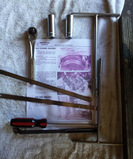
<cm400 valve adjustment tools>

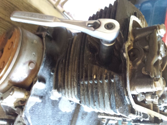
Gather up the tools you will need along with a copy of the appropriate service manual. Please note that it is not necessary to remove the engine from the motorcycle to perform this procedure, I already have this engine out so that I could do some some fabrication work & painting to the frame. This is the long delayed Project wAmmo bobber that I should have finished months ago, but now I am back on it with a vengeance. You will need to remove the fuel tank, gear shifter, and whatever other parts are necessary so that you can remove the valve cover & the left side crankcase cover. Once all of that is done then remove both sparkplugs.

<cm400 spark plug removal>

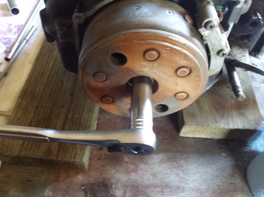
After you remove the spark plugs, switch sockets & turn the engine in the direction indicated by the arrow on the alternator rotor. The big rusty flywheel looking thingy you see in these pictures for those of you who have never seen one before. This one had to have some of the rust sanded off so that I could see the markings on it.

<honda cm400 alternator rotor>

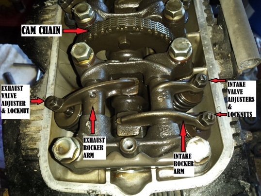
Turn the engine and watch for the intake valve rocker arm on the side you are adjusting to move down and then back up. These little Honda twins have a 3 valve per cylinder layout with 2 intake valves & 1 exhaust valve per cylinder.

<cb400 rocker arms illustrated>

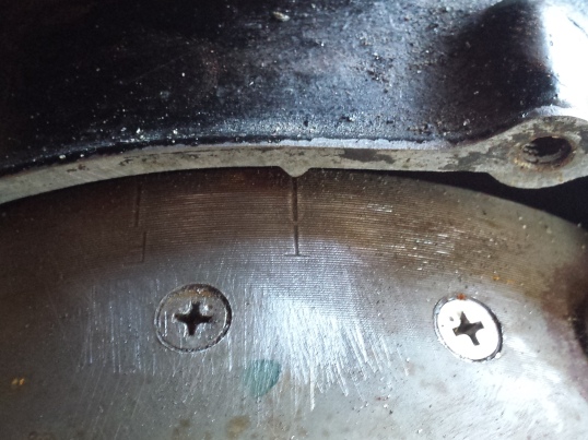
Once the intake rocker arm returns to the top continue to turn the engine slowly and line up the next “T” mark on the flywheel with the pointer on the engine case, as it comes around. If the exhaust rocker arm starts to move you have gone to far & must circle the engine all the way back around & start over. Do not turn the engine backwards to get to the timing mark if you miss it.


<Honda cb400 timing marks>

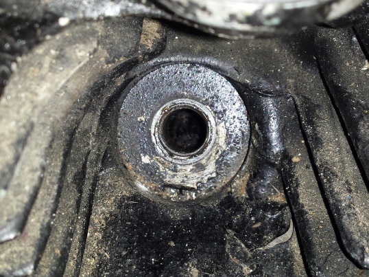
Then verify that the piston is indeed at top dead center. On this engine it is fairly easy to do just by looking into the spark plug hole.

<Honda cb400 piston tdc>

With the piston at top dead center for the cylinder you are adjusting both the intake & exhaust valves should a little bit of play in them unless the engine has severe wear or improper maintenance that has caused valve recession which will close up the gap. Too much lash is also detrimental to your engines performance and will cause your engine to tap very loudly. Too little lash will eventually lead to a burned valve if it doesn’t close completely.

Loosen up the lock nut for whichever adjuster you choose to start with, here I am starting on the exhaust side.

<cm400 exhaust valve locknut>

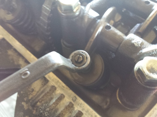
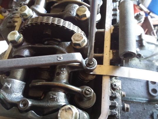
Then insert the proper size feeler gauge, loosening the adjuster with a flat screwdriver if needed.

<Honda cb400 exhaust valve lash>

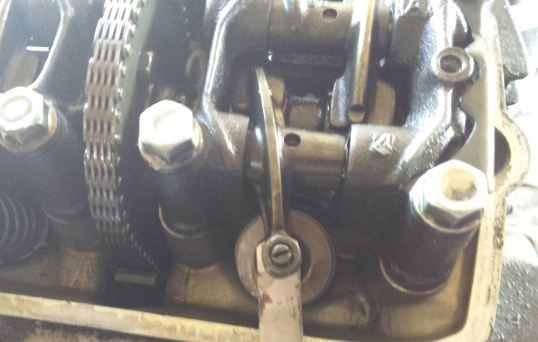
Then carefully tighten the adjuster screw & lock nut until the feeler gauge is able to be removed & re-inserted with just a little bit of drag, but the next size larger feeler gauge should not fit. It will be necessary to hold the adjuster screw with the screwdriver as shown below while you are tightening the lock nut. Be sure to recheck your lash after you tighten down the lock nut for good, sometimes you may have to readjust to compensate for the adjustment screw moving when you torque the lock nuts.

<Honda cb400 intake valve lash>

Once you have all of the valves adjusted properly replace the engine covers being sure to inspect & replace all gaskets & seals as needed.

Valve lash and some miscellaneous tune up specs are below:

Intake valve clearance 0.10mm +/- 0.02mm    0.004″ +/- 0.0008″

Exhaust valve clearance 0.14mm +/- 0.02mm    0.006″ +/- 0.0008″

Idle speed 1200 rpm +/- 100 rpm

Spark plug   NGK-D8EA  or ND-X24ES-U

Spark plug gap  0.6~0.7mm    0.024~0.028″

Oil capacity  3 liters    3.2 U.S. qt.s

Hopefully this has helped someone out.

Happy Wrenching!

Dirtbike Carburetor 101 Part Two!

Welcome back everyone,

At the end of the last class we ended with the carb sitting on the bench and the intake port in the head plugged to keep out dirt & small critters. Now let’s pull off the vent hoses and turn it upside down on the bench like this.

Take note of the pilot mixture adjustment screw that I have labeled here for you. I will be giving you a tip about it later in the lesson so be ready to refer back to this picture if you need to. Please remember these are not in the same place on all carburetors. I have seen them on the top and on the side depending upon the make and model. Some late model machines have them hidden under aluminum caps to keep you from tampering with them, but if you have a real problem you can remove the caps to repair it. Just be sure to replace them especially if you have to pass emissions inspections in your state. As usual I recommend you consult your handy dandy service manual for your motorcycle just to be on the safe side, because some carbs have more than one aluminum plug and you don’t want to remove the wrong one. Trust me I know….

Of course this bike has none of those annoying issues so let’s go ahead and take the screws out of the float bowl and look inside.

EWWW!

Now I am a fairly environmentally conscious guy, I grow organic veggies, the shop that I work in is powered by solar electricity, drive reasonably efficient vehicles etc. but you will never convince me in a million years that today’s gasoline is good for the environment. Once the lead was removed there really was not that much left to improve. There is no way  fuel that will rapidly break down into this toxic and corrosive sludge as fast as the fuel made in this day and time, can possibly be good for the environment. Just think of what it is doing to your vehicles as they sit in the driveway right now.

Let me get out of rant mode and get on with the lesson; here’s a shot of it with the float removed. You should be able to push the pin out to one side with a small punch and lift the float and float needle (float valve) out of the bottom of the carb.

So when someone tells you the float is sticking this is what they are talking about. Sticking floats are usually caused by either a piece of trash getting under the point of the float valve, or if the motor has been sitting by gasoline evaporating, and gluing it into place with a coat of gunk like you see here.

In this next shot I have removed the jets and the mixture adjustment screw. Even if you have a service manual handy, before removing the mixture screw, turn it all the way in slowly and count how many turns it takes to go all the way in. Write the number down somewhere, and then remove the screw along with the spring the washer and the o-ring that are in the hole under it.

You’ll probably have to dig for the o-ring using a piece of wire or a small pick like I did above.

At this point all of the metal parts are ready for a good long soak in the parts washer or carburetor cleaner until tomorrow. In fact the longer the better. Gather up some supplies.

If you have an air compressor and a parts washer you may not need the spray carb cleaner. If you don’t have a compressor it is mandatory even with a parts washer or a dip bucket of carburetor cleaner. For this bike I did pick up a carburetor overhaul kit. If your o-rings are all still in good shape and you can get all of your jets spotless you may not need it, but it is often difficult to clean the idle jet good enough to work again even with all of the right tools. If it’s my own bike, and I am broke that week, I might chance it, cause hey it’s part of the price I pay for this hobby. If it is your bike, you are getting new parts, because if it does not work, then I would be working on it for free and that would just piss me off. You would probably be upset at me too.

Here’s a teaser shot of everything laid out on the bench after cleaning, be sure to come back for the next lesson!

exploded view!

Click here to continue this lesson!