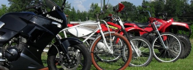
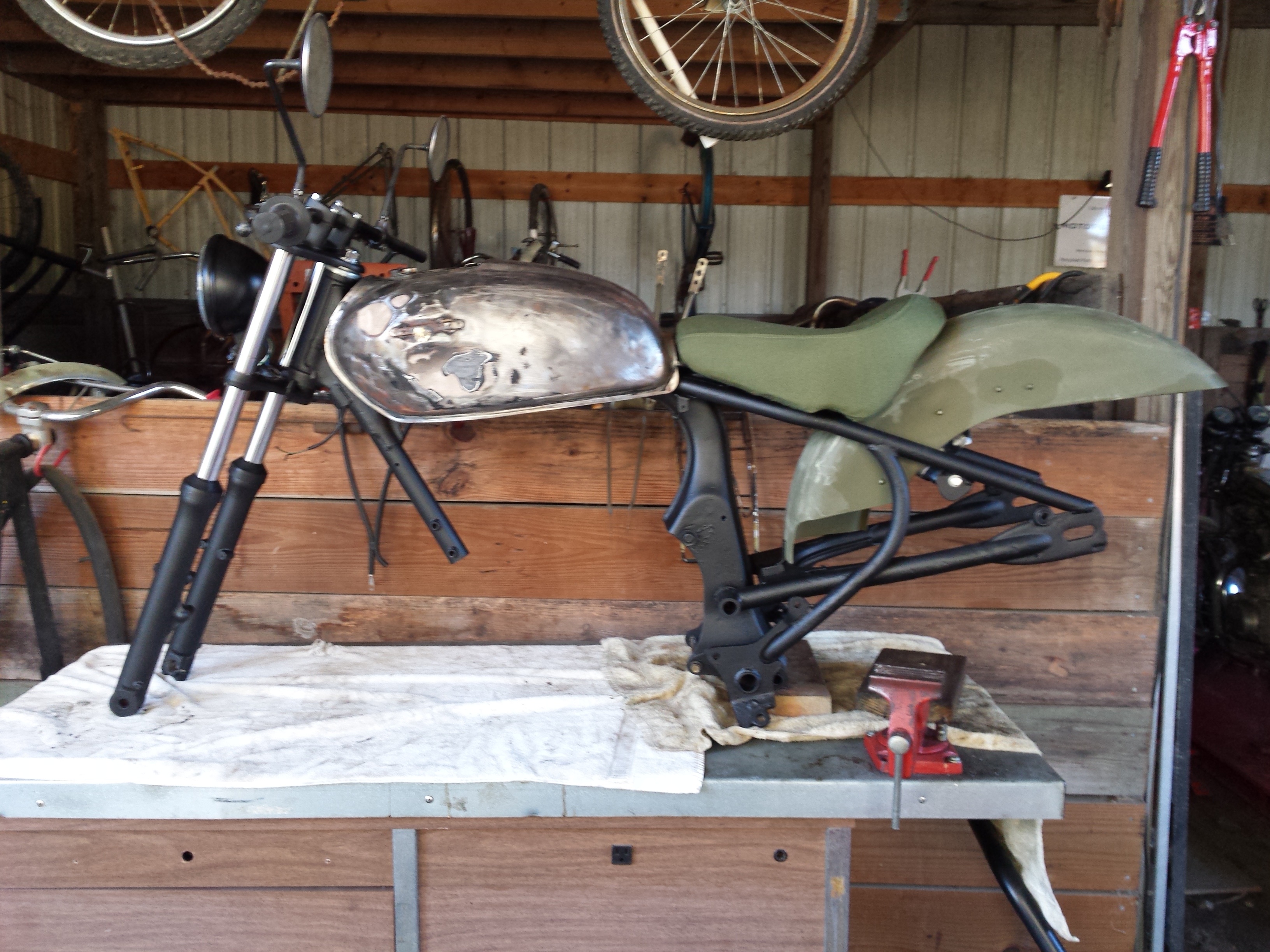
Finally started the repairs & upgrades to the old TS185. It was in dire need of new steering head bearings and brakes. A set of matching dual sport tires wouldn’t hurt either, along with a thousand other little things. So the day before yesterday I pulled it all the way down to a bare frame.
This is not going to be a show quality restoration by any stretch of the imagination. You may have noticed that the title of this post is The 20 Foot Restoration. If you’ve never heard that term before it describes a vehicle that looks really good from a distance of 20 feet or more, but when you get up close you can still see the dings & other imperfections.
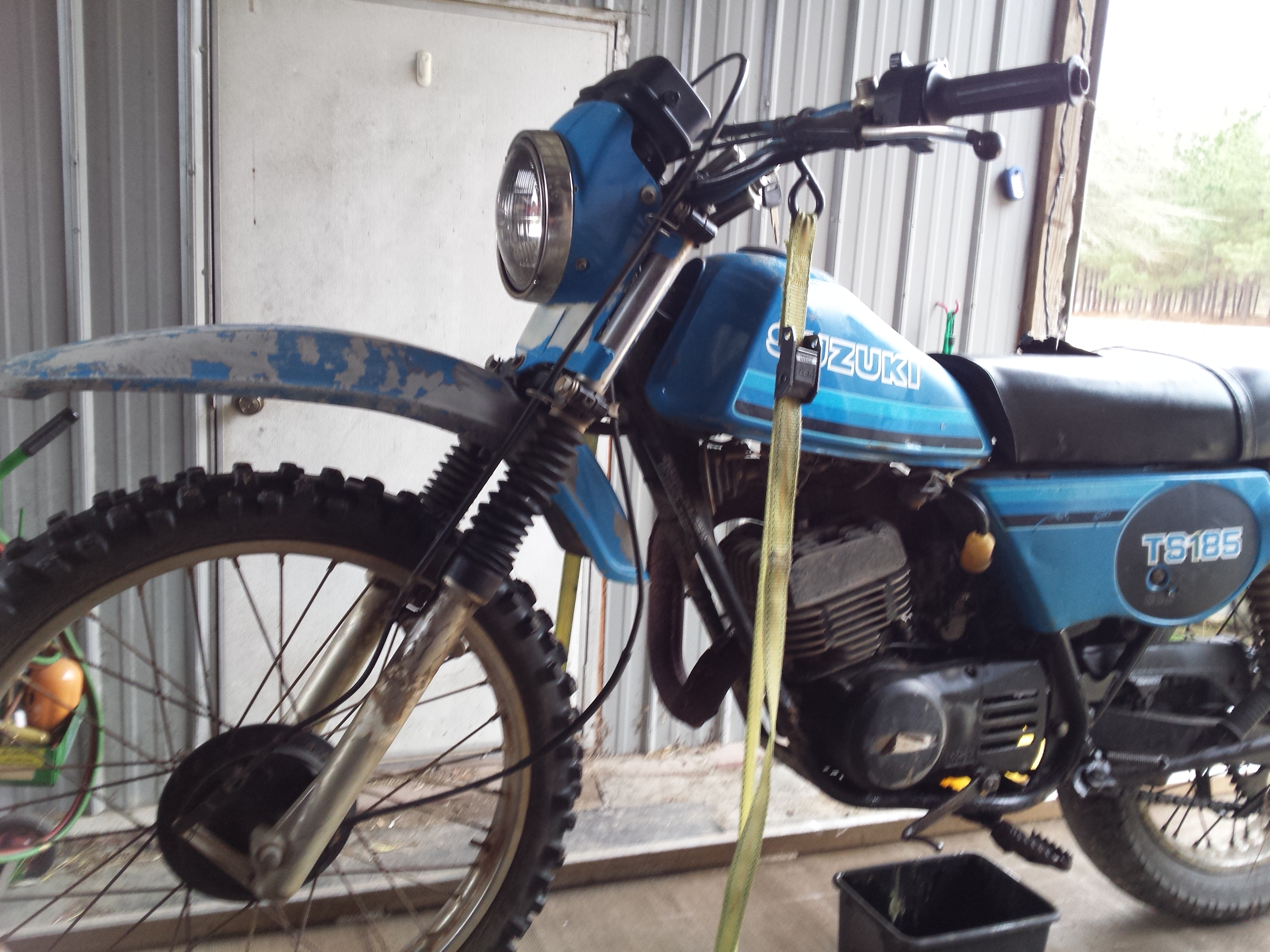
If the skid plate had been removable I probably would have left the engine in the frame for all of this as it runs excellent. But the skid plate is an integral part of the frame, and the area between it and the engine was packed with a mixture of red clay mud & two stroke oil. Plus there was some damage to repair.
After getting it cleaned up reasonably well, I took some body hammers to it, straightened it up some, and the welded all of the broken bits back together. Then I hit it with the wire brush & sandblaster before shooting a coat of rattle can primer.
All of the frame bits & pieces are painted with some some cheap spray on truck bed liner, while parts such as the shock bodies etc. are being done in brake caliper paint. I disassembled the shocks & dropped the springs into a bucket of metal rescue to soak overnight. they’re not perfect but they look a lot better.
After 2 days of hard work this was my stopping point last night, this morning I am going out to detail the engine as much as I can without actually taking it apart. and will continue the reassembly of this poor old thing.
In my recent post Twin Leading Shoe Drum Brakes, I went over the basics of servicing a set of front brakes from an 81 Honda CM400E, & while I feel that it was a decent article from a how to standpoint, it was pointed out to me that someone who was completely new to the world of vintage motorcycle or do it yourself mechanics might not fully understand that I was trying to convey so I thought that it would be a good idea to go over the basics of the different type of vintage motorcycle drum brakes. For the purpose of this we will examine internal expanding shoe brakes, there are some ancient motorcycles & some minibikes that use a completely different drum brake style with an external brake band around the outside of the drum and I’m not going into that here unless you give me evidence of overwhelming popular need for explanations of external band brakes. Below you will find a few illustrations along with some brief explanations of mechanically actuated single leading shoe & twin leading shoe vintage motorcycle brakes. Just for grins I’ll show you an exploded illustration of a four leading shoe drum brake at the end of this post.
First let’s examine the single leading shoe drum brake. This is the type that you are most likely to encounter on motorcycles and atvs that utilize drum brakes at one end or the other. In fact there are still some lower end bikes that still use this system today. It is simple & it works.
When the brake arm is moved the brake cam pivots pressing the shoes into the drum generating friction to stop the wheel from turning. You may have noticed that I have the shoes marked leading and trailing and here is why. with the drum rotating in a clockwise direction the bottom shoe is pushed away from the brake cam by the rotating drum thus forcing it against the brake pivot post and the drum with greater force. The front or leading edge of the brake shoe is the first part of the shoe that the rotating drum passes over as it turns whereas the trailing edge is the last edge of the friction pad in the path of drum rotation. The top shoe in this illustration is labeled the trailing shoe because the trailing edge of the shoe is forced up into the drum first. Because it is not being pushed into a fixed pivot point by the rotation of the drum, the force generated tends to push it back towards the brake cam instead of pushing it more tightly into the drum. This means that the trailing shoe generates less stopping force than the leading shoe. There are a few advantages to this design with simplicity & reliability being at the top of the list. Another huge advantage to this design is that when you reverse the direction of wheel rotation, the trailing shoe becomes the leading shoe & the leading shoe becomes the trailing shoe. Why is this an advantage you may ask? Simple you get equal braking force whether you are going forward or reverse. While this is not that big a deal on a motorcycle it’s very important on vehicles such as atvs, tractors etc. that have reverse gears and travel backwards under power.
Up next let me throw up an illustration that I created of a simple twin leading shoe brake.
You will notice that there are still two brake shoes inside the drum but now there are two brake cams, two pivot posts, & two brake actuating arms joined together with a linkage. When the brake arms are moved it raising the leading edge of both shoes into the brake drum. Remember the advantages that the leading brake shoe has in stopping force that I told you about earlier? Now both brakes shoes are leading shoes giving you the maximum amount of friction possible from a drum brake design. This is the advantage to this design, increased stopping power. The disadvantages are that it is slightly more complicated and that it requires careful adjustment of the brake arm linkage to ensure that both shoes contact the drum at the same time. If the shoes do not open at an equal rate then only one of them will touch the drum under use giving you even less stopping power than a single leading shoe brake system. Also if you reverse the rotation of the wheel the twin leading shoes become twin trailing shoes, giving a reduced stopping power in reverse. On a motorcycle this doesn’t really matter though.
In the blog post about twin leading shoe drum brake I stated that they were the ultimate development in vintage motorcycle drum brakes, well that is almost true. There is a system that is capable of generating even more stopping force than that, the four leading shoe drum brake that was used in some exotic racing machinery. I shall not go into a huge amount of detail here except to say it is basically a pair of twin leading shoe systems mounted back to back on a common hub. I cribbed the image below from TheVincent.com.
If you are fortunate enough to own such a fine machine as an antique, Vincent, Brough, or MV Augusta racebike that uses 4 leading shoe brakes and you (or your staff mechanic) are not able to get it sorted properly, then load it into the enclosed trailer that you keep attached to your Land Rover, or Cayenne and have your butler deliver it to me along with a sackful of large unmarked bills and I will be glad to set it up for you, including a small amount of testing at a local track to make sure they are operating correctly.
Since I first posted this a couple of days ago it was pointed out to me that this article was not quite as beginner friendly as my normal do it yourself articles about explaining WHY you do some things. So if you don’t know the difference between a single leading shoe brake & a twin leading shoe brake or even how to identify which one you have or just to learn how they work please go to More About Vintage Motorcycle Drum Brakes and then come back to this page.
Twin leading shoe drum brakes are the ultimate development of motorcycle drum brakes. By using two lever arms and two cams to raise the leading edge of the brake shoes into the rotating drum they were able to generate a greater stopping force than a standard drum brake which pushes the leading edge of one brake shoe & the trailing edge of the other shoe into the drum. It was discovered early on that the shoe with the leading edge being forced into the drum generated much more friction than the trailing shoe. So until the development of powerful reliable disc brakes in the 1970s the twin leading shoe motorcycle brakes were pretty much the ultimate performance set up. Even after their performance was eclipsed by hydraulic disc brakes they were still considered adequate for small & medium sized machines right up into the early 1980s. Today there are still a few low end bikes fitted with drum brakes on the rear, but they are of the standard type, as even the low buck machines rely on powerful front discs for most of their stopping power. As far as I know today twin leading shoe motorcycle brakes are only found on antique, vintage, and custom bikes.
As always don’t forget that you can enlarge any picture on this blog by clicking on it.
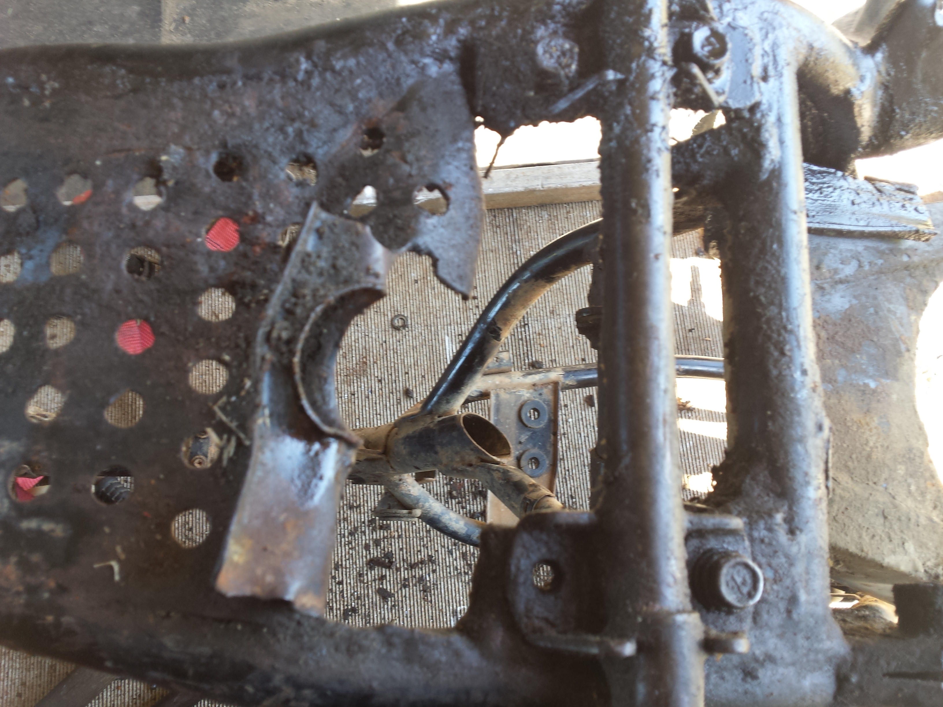
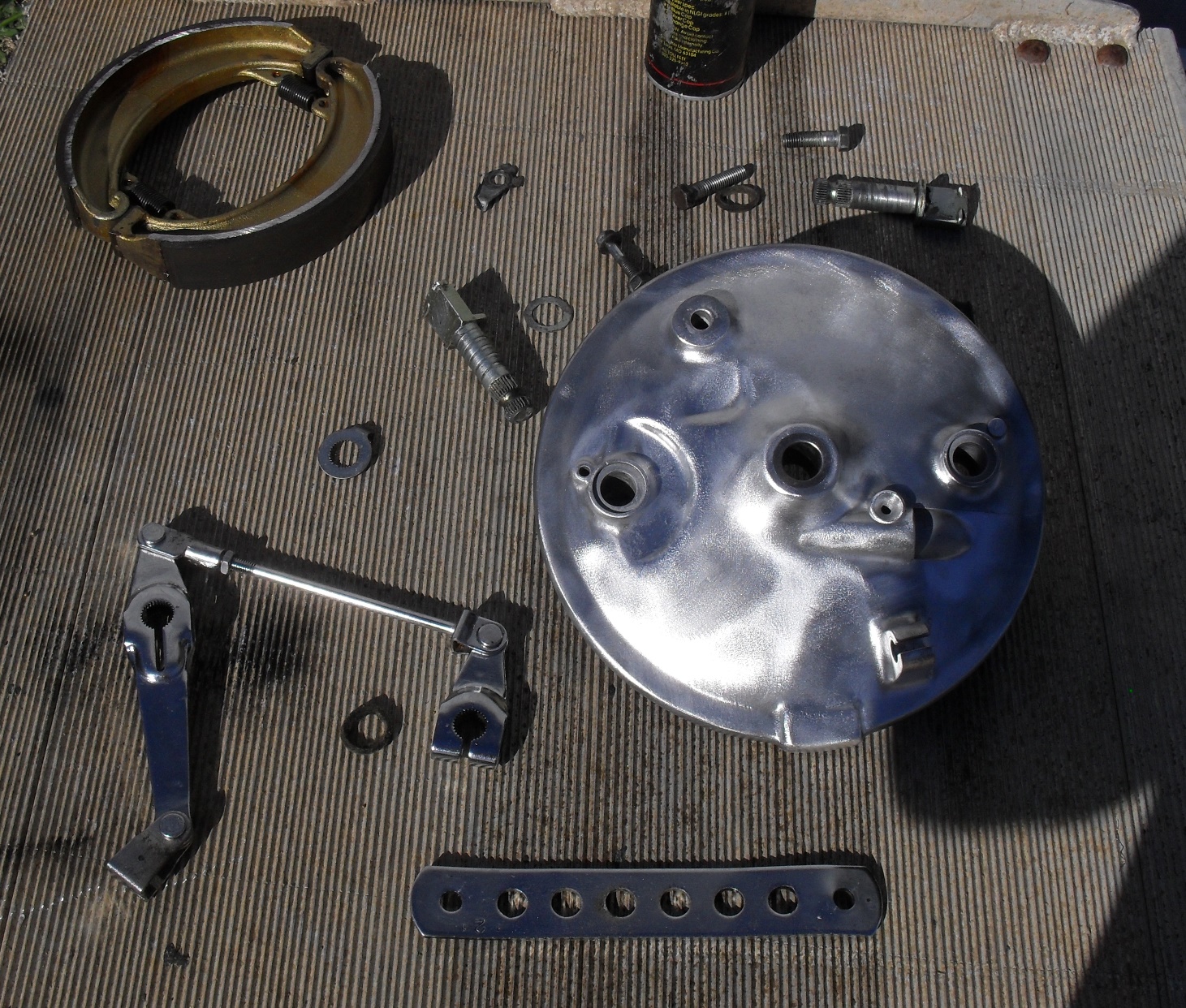
What we are going to look at today is an example of what may be the last of the of the factory installed twin leading shoe motorcycle brakes. The nasty cruddy looking part you see above is from an 81 Honda CM400E. The “E” stood for economy. The CB & CM variants of this bike got disc brakes on the front. By 1981 these were considered obsolete and were used on this model as a bit of parts bin engineering to meet a price point. This particular front wheel & brake backing plate had been painted at least 3 times in different colors What you see in the picture above is after using some aircraft peeler & some light soda blasting to clean it off a bit. Then I disassembled it and and dropped all of the chrome bits in the Metal Rescuetub and put the rest of it in the parts washer before wire brushing the backing plate. Please note, if you are doing a restoration you do not want to wire brush aluminum parts like this but this one is going on a rough edged custom and the brushed finish will be perfect for it.
This is an exploded view giving you a look at the typical parts of a front hub using this style of brake.
On this one I will not be reinstalling the speedometer gear as my plans call for a custom electronic speedometer. The first thing to do is apply a light coating of high quality grease to the shafts of the brake cams and push them into the backing plates.
Second part is to put the clean, lightly oiled felt seals into place as illustrated below. While I am sure there is probably a specified oil for this I’ve always just used whatever was handy in my oil can and have never had any trouble. That being said I am not responsible for any trouble you may have if you do not research and use the factory recommended oil.
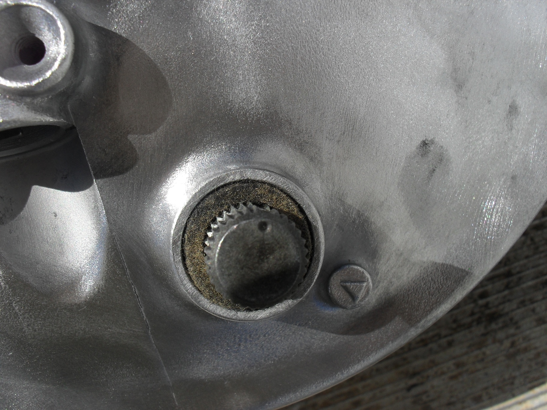
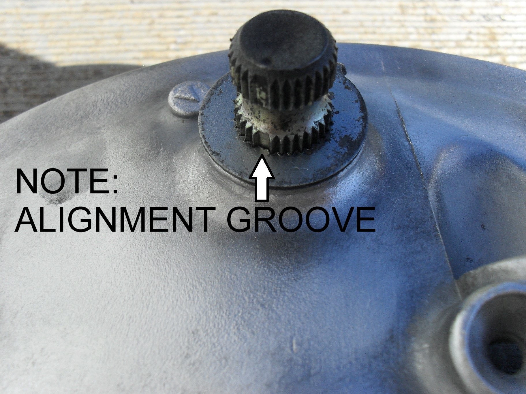
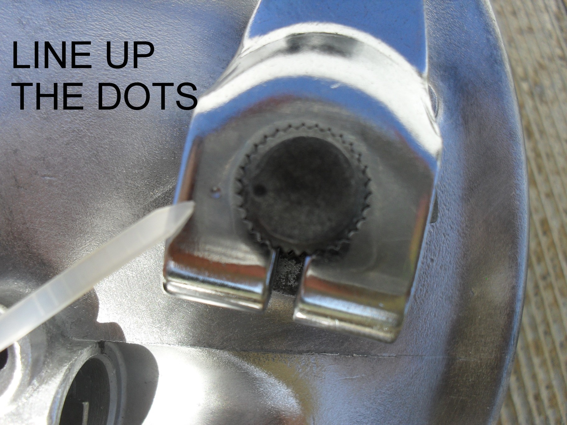
Third step here is to slide the washer with the wear indicator tab back down onto the brake cam over the felt on the side that you removed it from which should have a pointer cast into it like in the picture below. This little part has splines and has an alignment groove so that it will only fit one way. It it doesn’t just just slide back on you have it turned the wrong way and need to move it around the until the wide spline lines up with the wide groove.
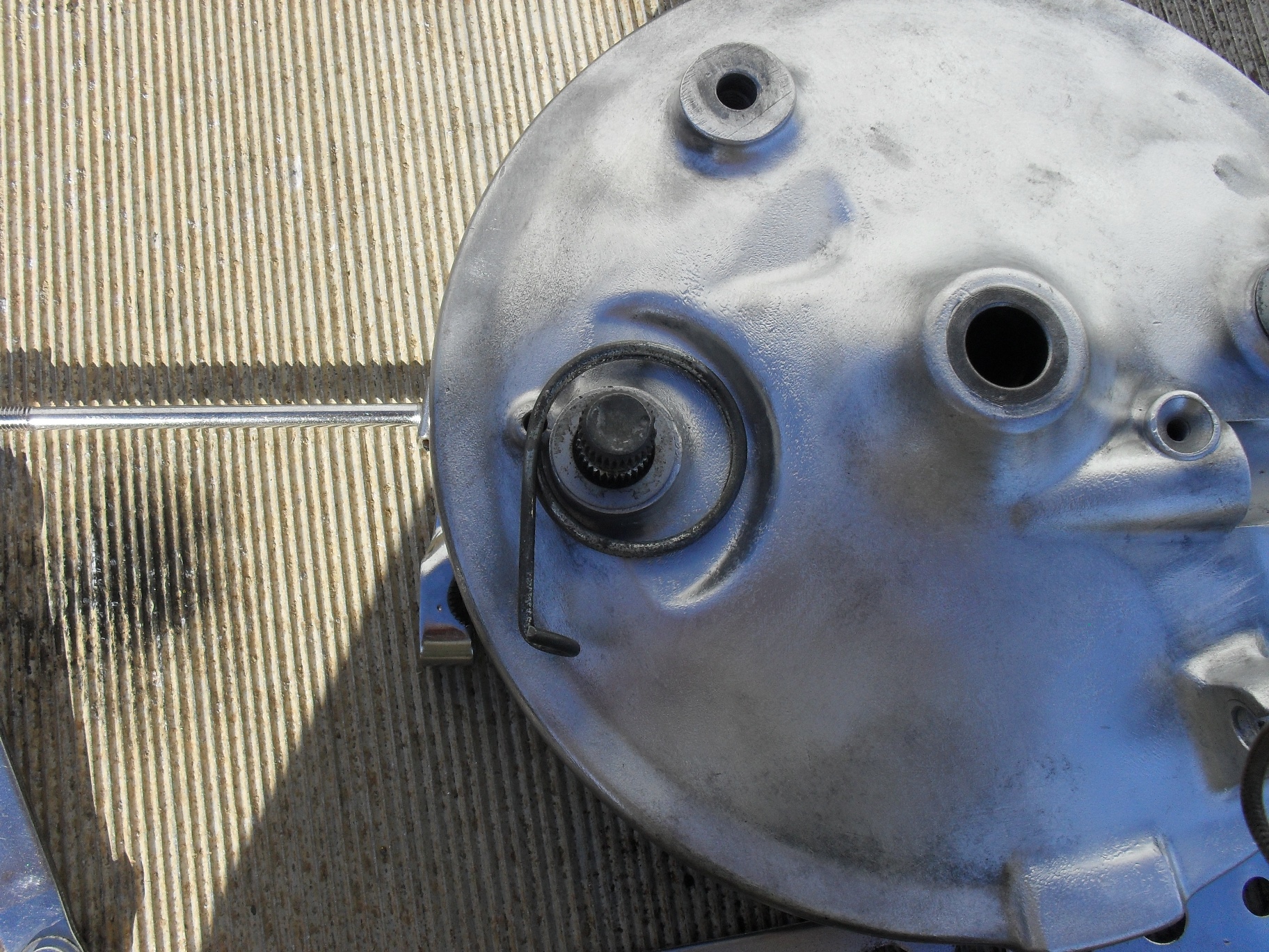
A plain thin washer slides down to cover the felt on the other side of the axle hole.
The external return spring is dropped into place next.
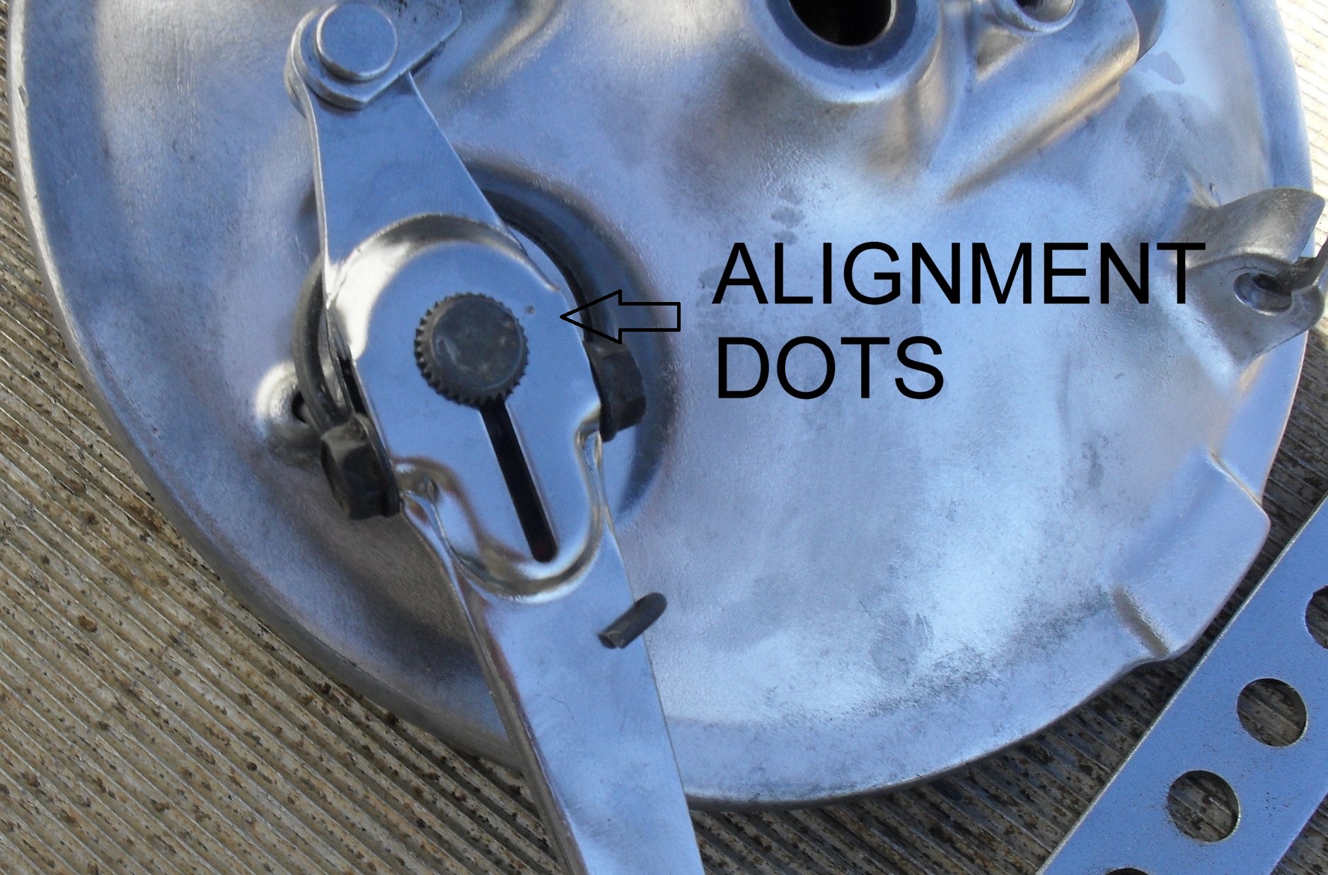
On of the really nice thing about most old Japanese bikes are the presence of dots on the brake cams & arms to help you line them up correctly the first time.
Put the arms on one at the time aligning the dots. I normally have brake rod loosely installed between the two arms before assembly just because I think it is easier than connecting the two brake arms afterward. If it is easier for you to do it the other way then that is fine too.
Do not tighten the lock nut on the brake arm yet! Install the brake shoes first!
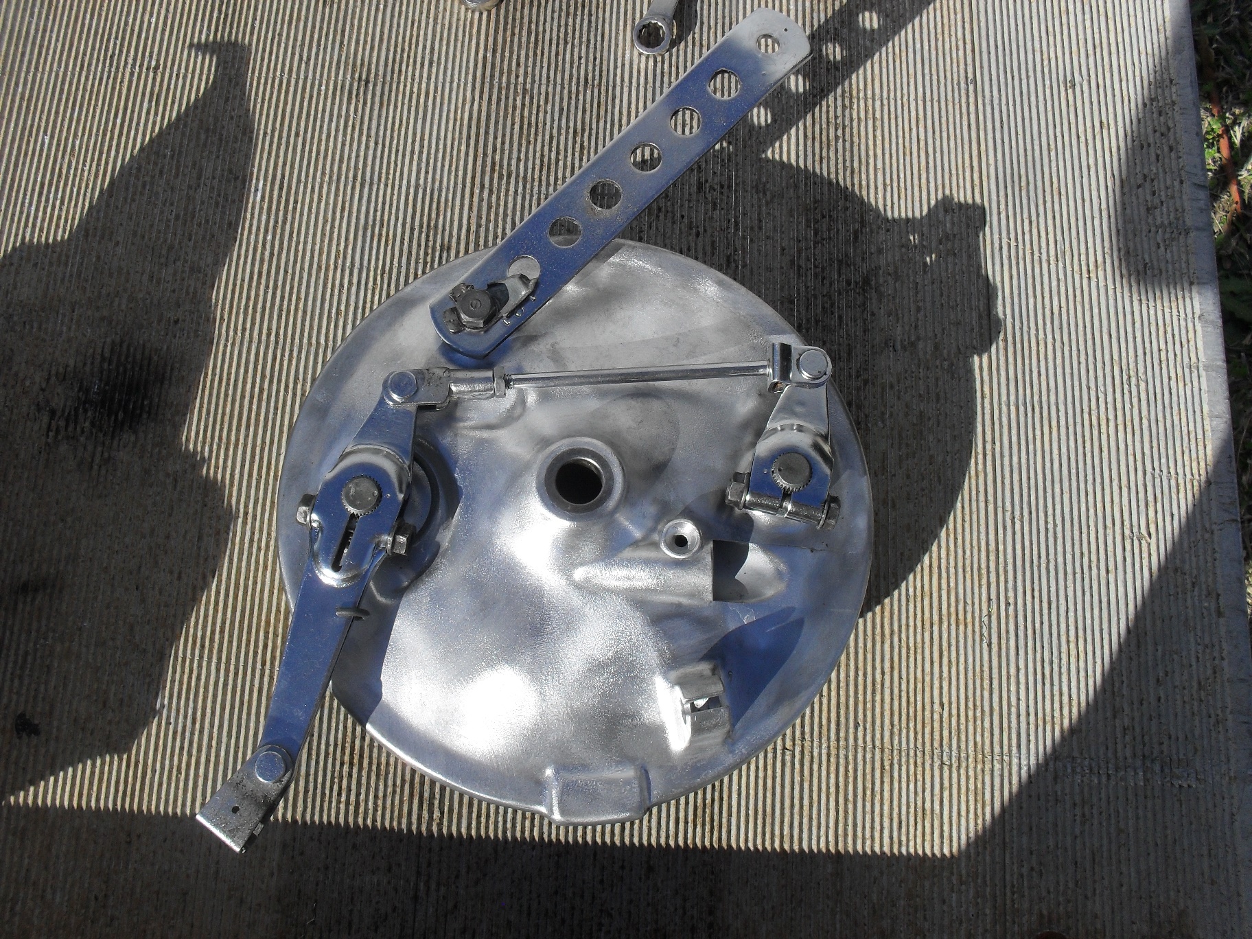
Adjust the brake rod as necessary to get both shoes to move at as close to the exact same time as possible. If you are a real demanding performance nut build yourself a jig and use a couple of dial indicators to ensure that the pads are moving together exactly. For the vast majority of us eye-balling it will work fine and any teeny little mismatch that occurs will be wiped out within a couple of stops
Now you can tighten down that lock nut. Here’s a little video to show you how the cams move the shoes when the brakes are actuated.
Now its time to get to work on the rest of the front wheel so that it can be installed on the front of Project wAmmo!
It’s time for another Project wAmmo CM400 update. Let’s start with my confession that I lost interest in the project for a little while and was really short on time for it. Had some issues with getting the frame sandblasted so I wound up bringing it back home and hit the frame with some paint remover and went over it with my little hand held sandblaster before coating it with spray on truck bed liner. Did the same thing for the tank before brazing up a couple of damaged spots on it and sealing it with Caswell Epoxy Gas Tank Sealer. I also wound up replacing the fork because I was unable to identify the one that was on it to get the proper repair parts so I replaced it, and installed a set of tapered roller steering head bearings for good measure.
I got the modified Harley solo seat covered in olive drab Cordura fabric to match the overall theme planned for the bike.
Even though the engine would start and run okay, compression on the right cylinder was consistently 50 psi less than the left cylinder. Even after adjusting the valves (click here for the proper procedure) which didn’t help, and putting some oil in the cylinder to see if it would come back up temporarily indicating worn rings, the right side was still 50 psi lower than the left side so I went ahead and pulled the engine apart for a top end overhaul.
The problem turned out to be that the oil rings were frozen to the piston and the gaps were aligned on the top 2 rings preventing them from sealing. The downside to this bike originally being such an artistically created “natural” ratbike is that it was incredibly nasty. Here I am soda blasting the cylinder to clean it. Yes that is the cheap hand held sandblaster
and it works just fine with blasting soda, so if you’re on a budget & just need to clean a few small parts without damaging them the way sandblasting can try this. Just do not hit any gasket mating surfaces with the soda.
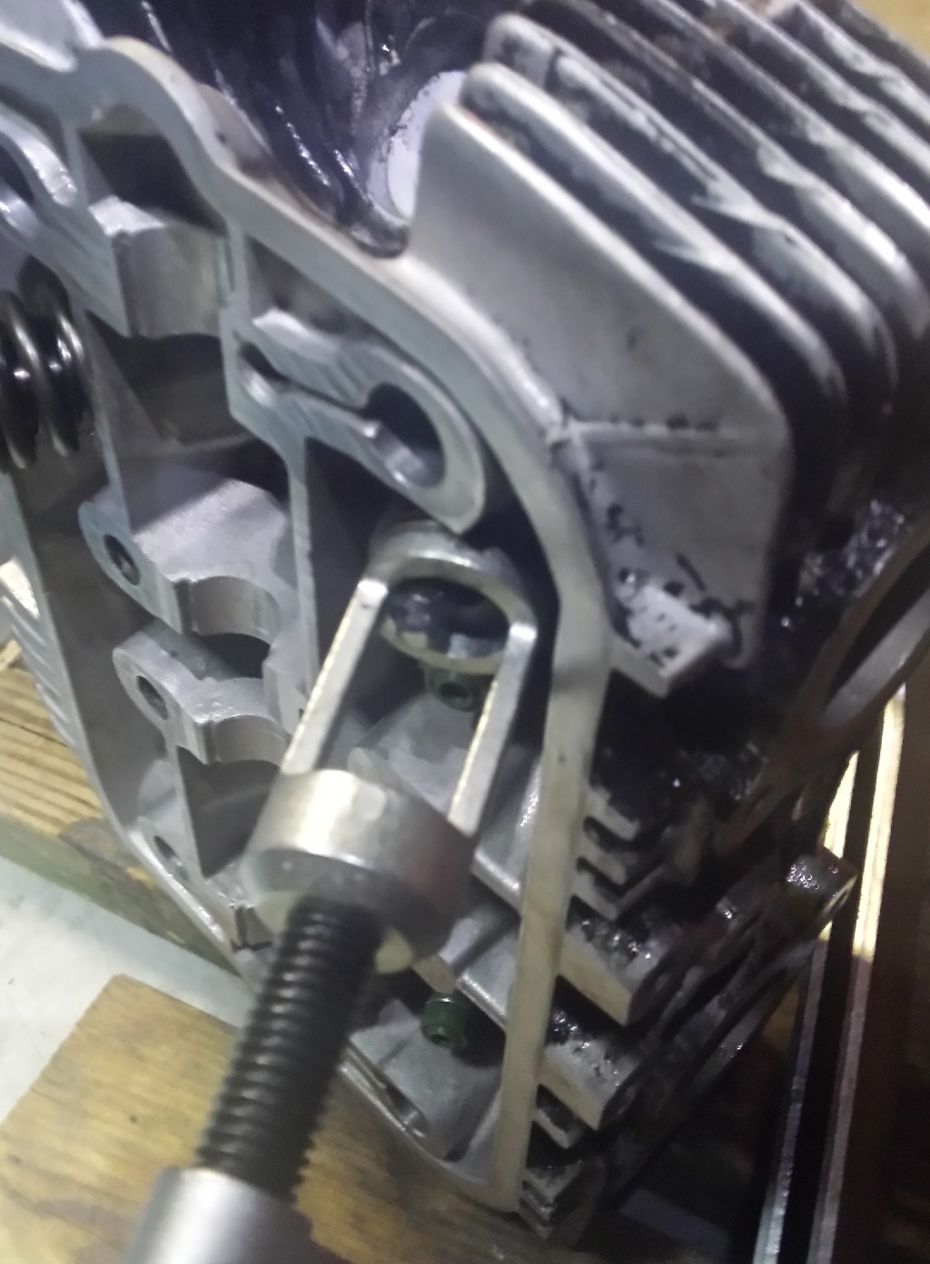
Once everything was cleaned & honed I taped off the mating surfaces so that I could spray on some Duplicolor cast iron gray engine paint.
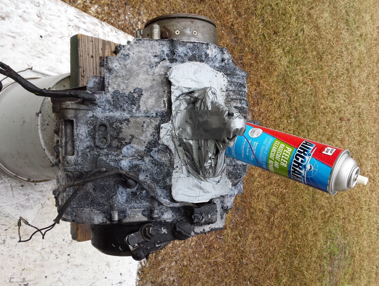
The original clutch cover will be replaced with this good used one and since I was not splitting the cases for a full overhaul I sealed up the bottom half of the engine with duct tape so that I could degrease it and remove the existing paint.
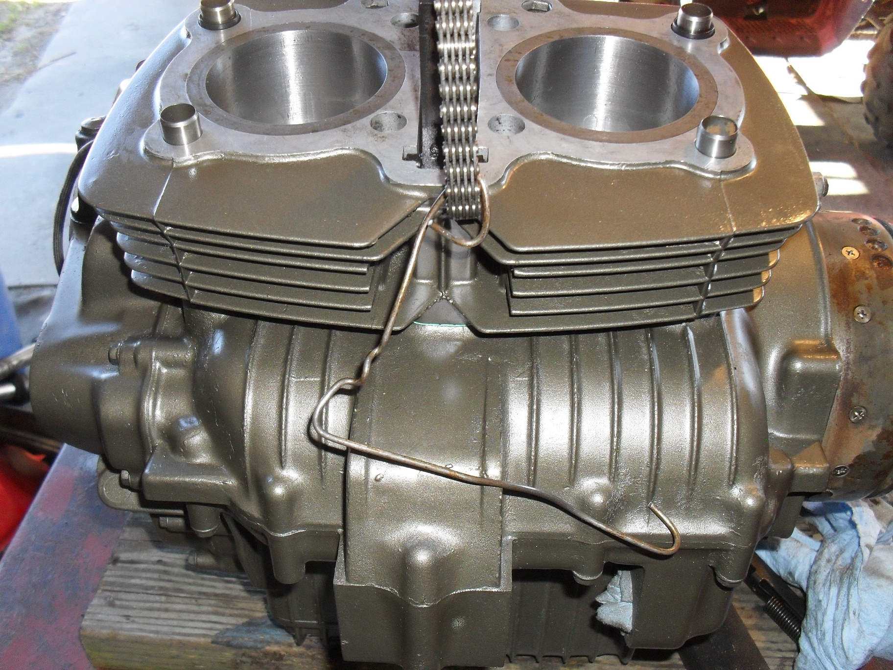
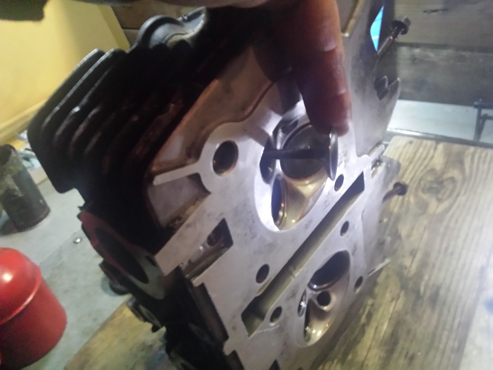
Since the head needed a good clean up, it became the subject of a head service tutorial that you can read by clicking here. The next picture is of the original pistons with new rings ready for the cylinder to be re-installed. The blocks of wood held the pistons up and level while beautiful assistant slid the cylinder slowly into place while I compressed the rings.
This looks a lot better than the before picture doesn’t it? Once I got the head back on it was time to line up the timing marks for the crankshaft & camshaft as shown below and put the camshaft back in.
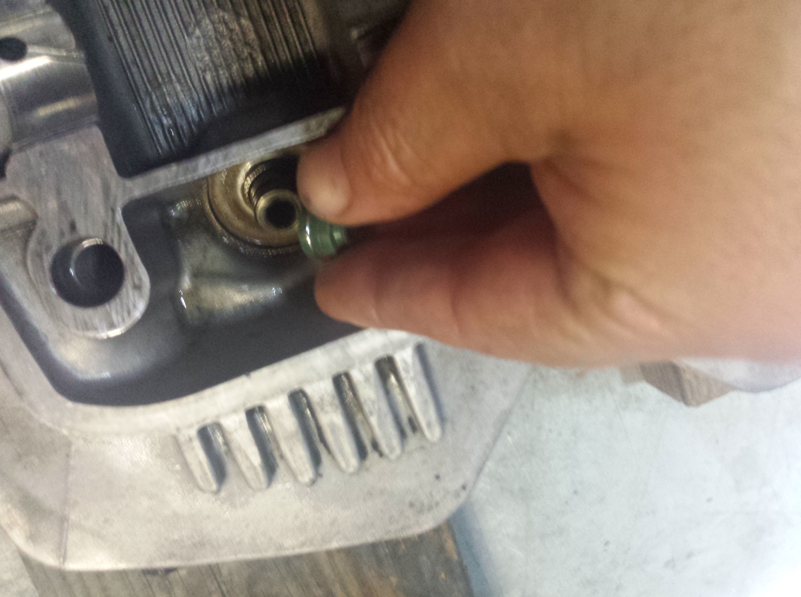
Afterwards it was just a matter of putting the rest of the parts back on and torquing everything down properly. Don’t forget to fill the oil pockets under the cam lobes with oil before putting the rocker box cover back on.
The engine is now ready to reinstall, I am going to leave the rotor cover off until later, ditto for the new clutch cover.
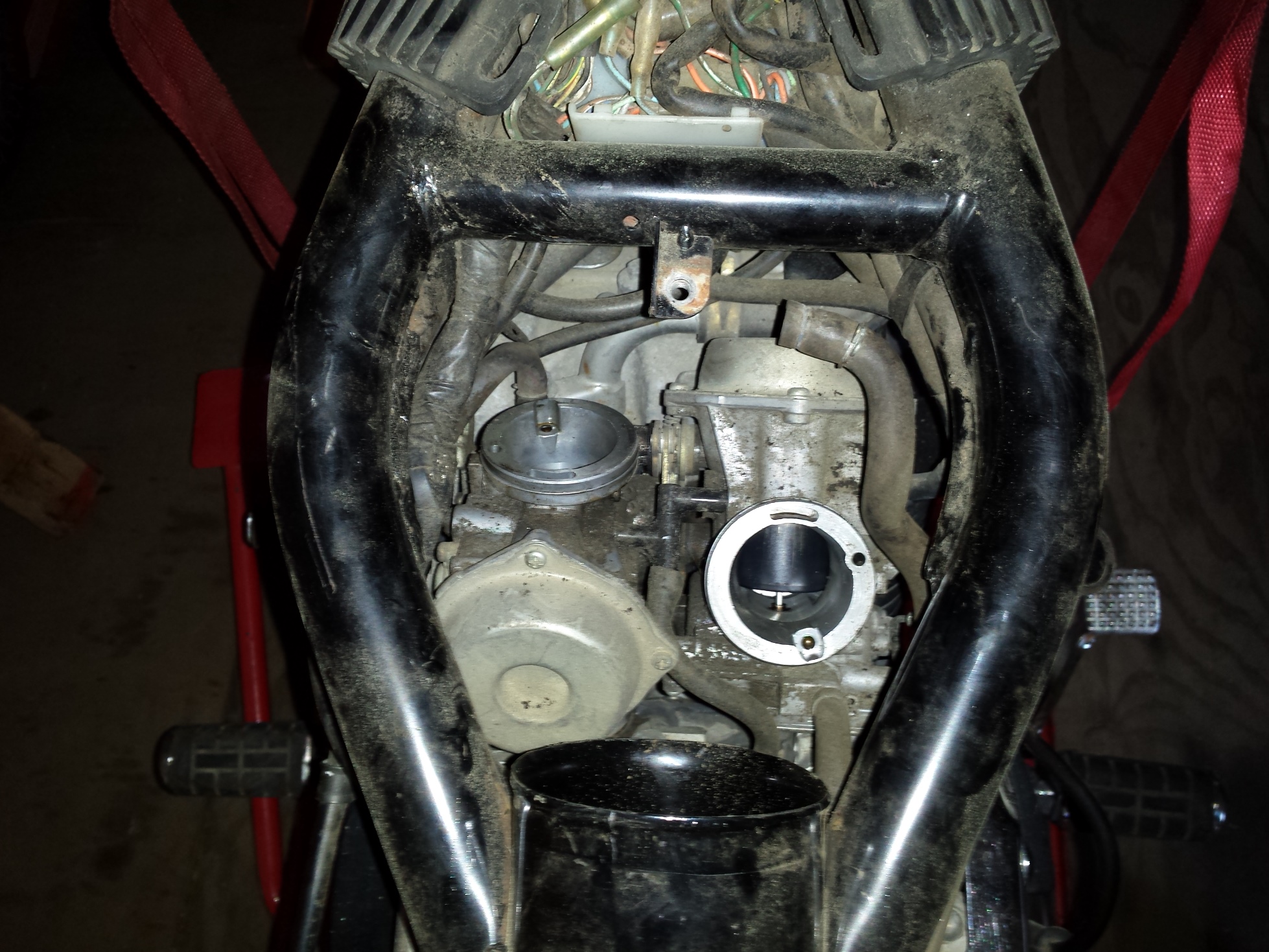
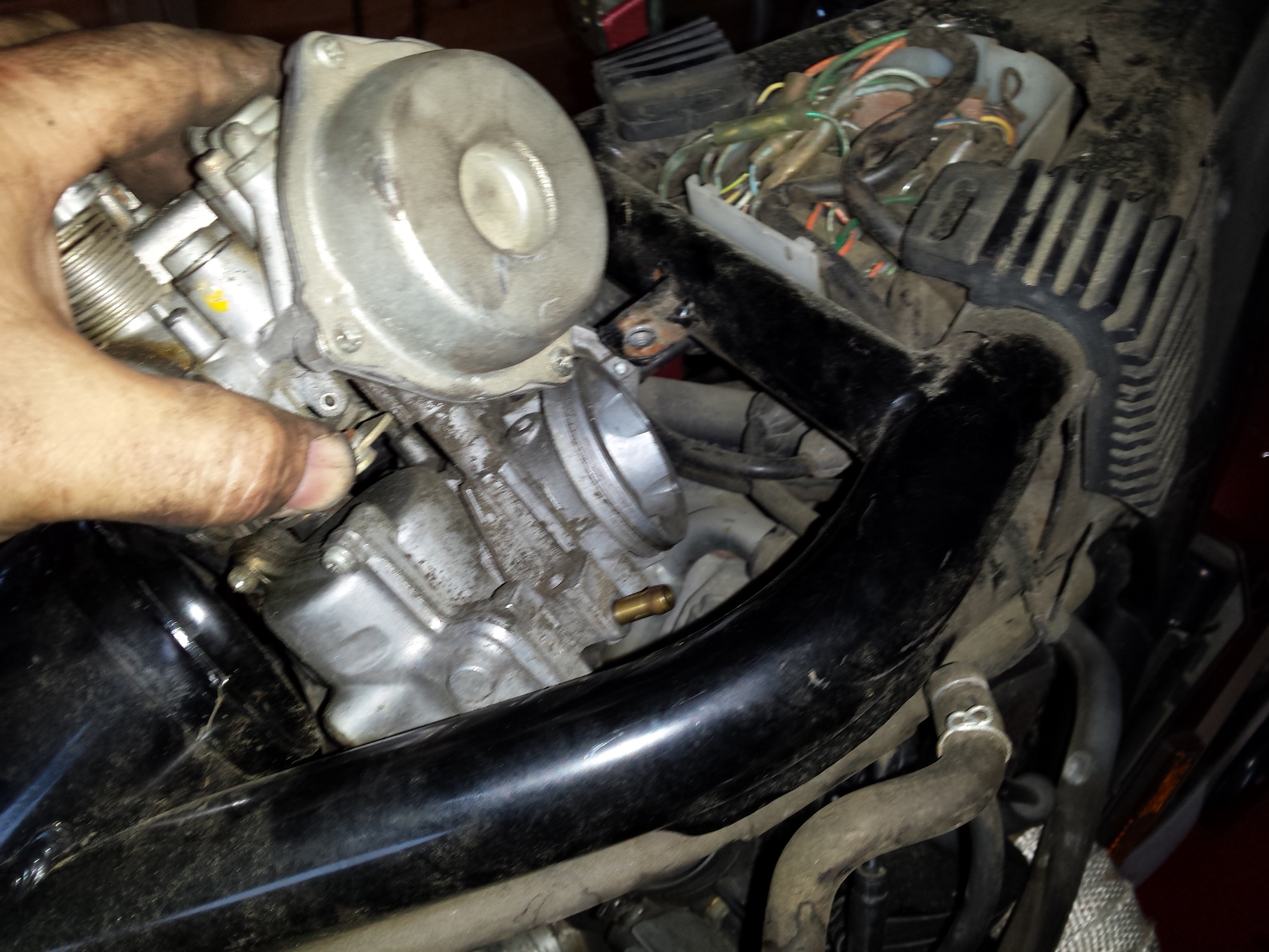
Now the engine is sitting back in the frame. The intake spigots are new replacements for the damaged originals.
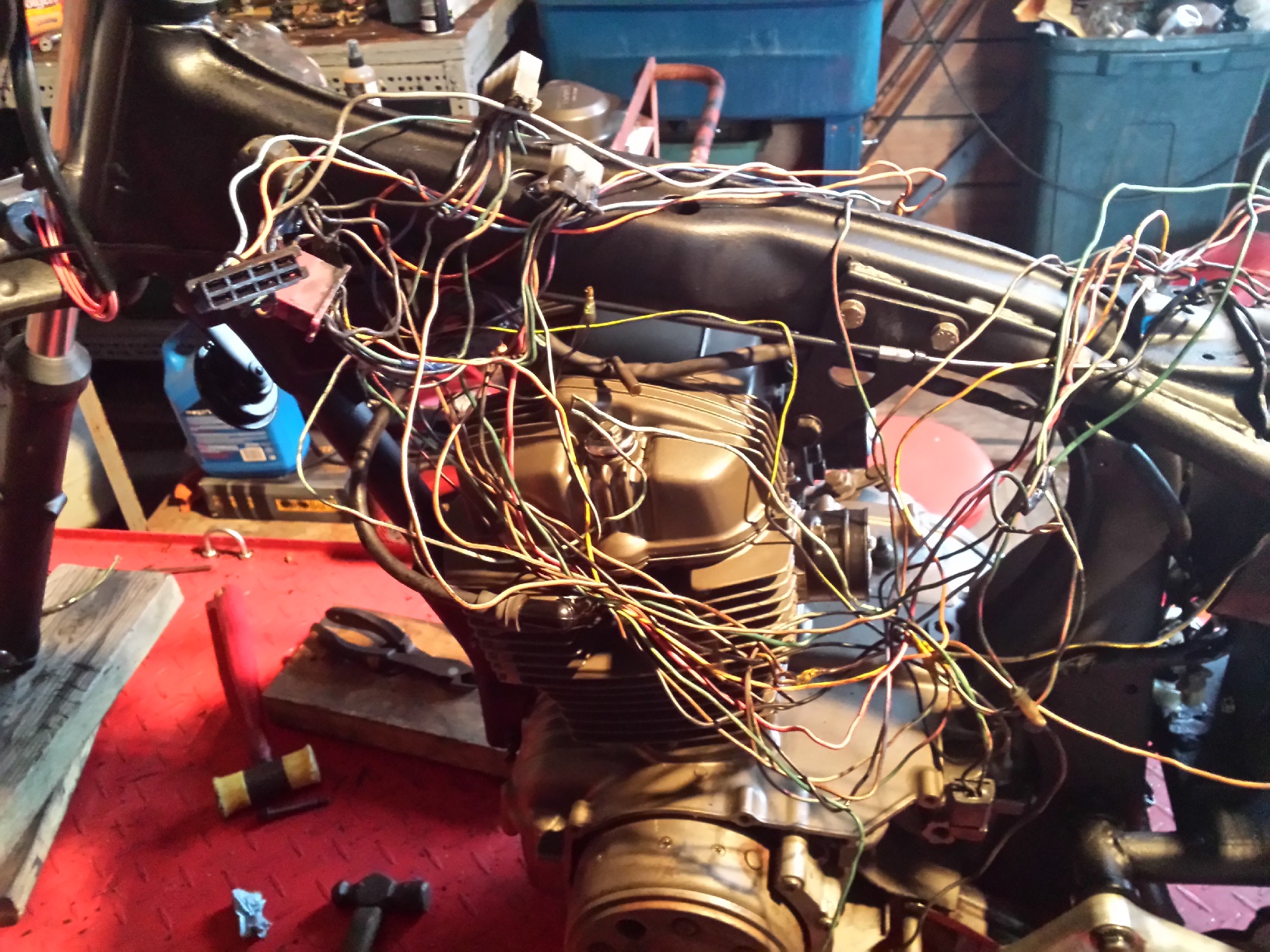
I like puzzles
Now its time to sort out the wiring harness. Sometimes it is easier to start from scratch but for right now I am going to attempt to reuse at least some portions of the factory harness.
Normally on a custom motorcycle one would attempt to hide such parts as the regulator rectifier but since I am going for a post apocalyptic paramilitary look on this machine it is bolted to the side of the rear fender out in plain sight.
Once I get the wiring sorted out and get the wheels back on it’ll be time top restore this set of CV carbs. I will probably do an in depth post on that process when the time comes.
D.I.Y. motorcycle head service is possible for the home mechanic at times, under the right circumstances. Of course if you are one of those fortunate individuals who happens to have a fully equipped machine shop and know how to use it you can do anything. But for the ordinary person restoring an older motorcycle or atv that wants to save a buck or two it is still possible to do an acceptable job provided certain conditions are met.
My patient for this job will be the CM400 that I used for the valve adjustment tutorial a couple of weeks ago. After adjusting the valves and putting oil in the cylinders it still had about a 45-50 psi difference in compression from the left to right sides so I pulled it apart for a top end overhaul. It turns out that the right cylinder had oil rings that were stuck from sitting and that the gaps were aligned on the other two rings.
Before disassembling it, I cleaned the head fairly well and removed the carbon from the combustion chambers. This makes handling the parts much nicer and inspection much easier. No matter what method you use to remove the carbon do not allow any type of abrasive or wire brush or scraper to contact the flat sealing surface of the head. Yes I know you may have to use some type of scraper to remove the gasket residue from the head but be very careful not to scratch or gouge it in any way. I actually used soda blasting to clean this head but made sure not to hit the mating surfaces with it.
Now I must make a couple of quick disclaimers here. First there are some defects that if discovered during the inspection process that will mean you need to take your head to a machine shop to be repaired anyway. Second, unless you own a set ball micrometers to check them with, you will basically be guessing that the valve guides are okay based on the condition of the valve stems. Chances are that if like me, you are working on something old but with relatively low mileage they are okay BUT it is not guaranteed and excessively worn valve guides can cause oil consumption & smoking even with new seals. Third, this is not the high performance option, if you are building a hotrod and looking to squeeze every last drop of performance out of it you can then I suggest you contact a reputable high performance machine shop for a good 5 angle valve job and new valve guides. This is to get your old heap running as good as possible for the least amount of dough you can spend. The fourth and last disclaimer is to always put safety first in the shop. You will be dealing with strong springs under compression. There is a chance that a tool could slip releasing a spring to go flying out at high speed and hit you or to pinch your fingers between the spring & the tool. Only use a good quality valve spring compressor
in good condition, make sure you read the instructions that come with it, & wear some eye protection too.
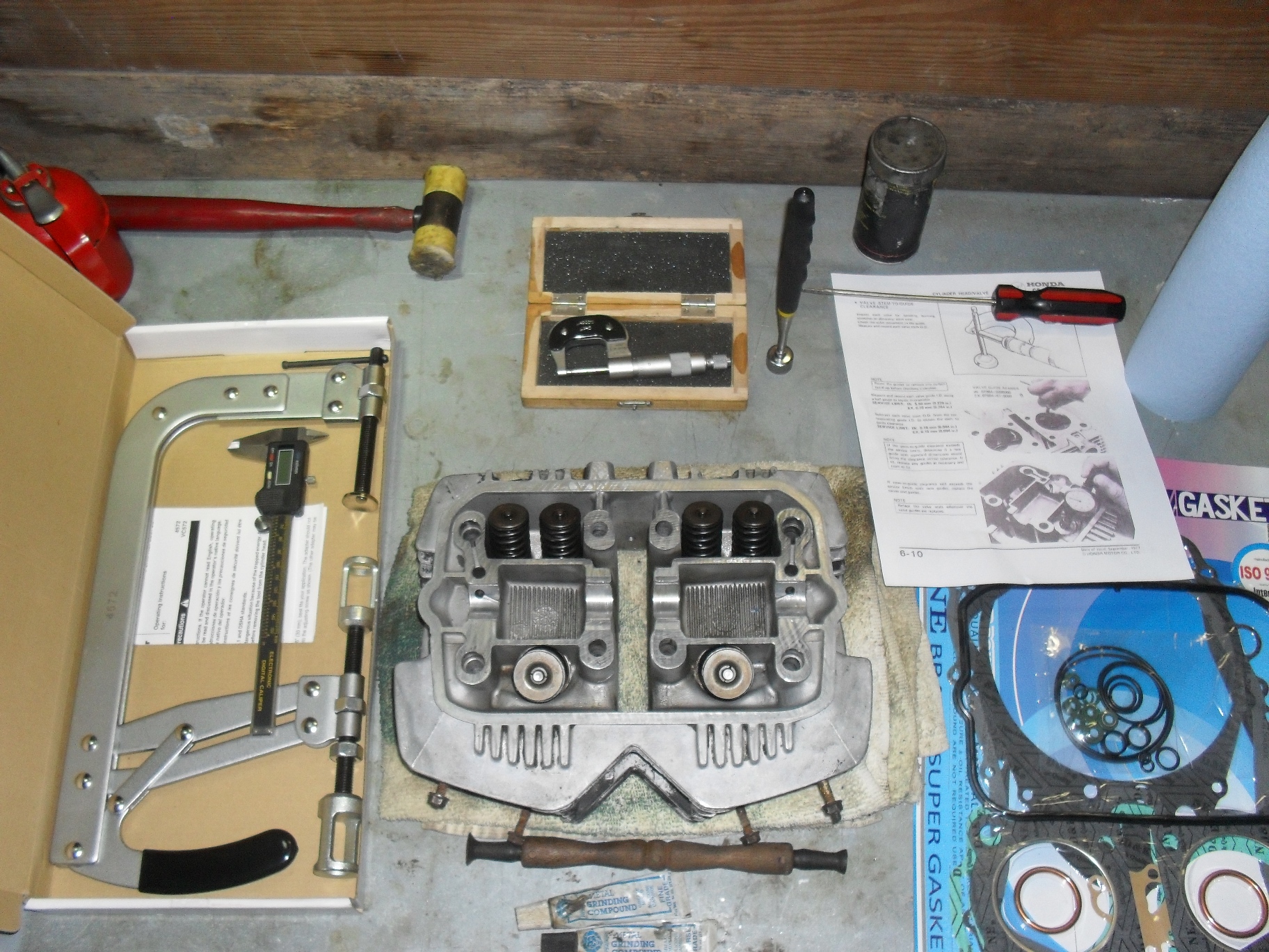
Even so there are some specialty tools you will need to get if you do not have them. In the picture above at the bottom center the thing with the two suction cups on it is a valve lapper with 2 tubes of grinding compound one coarse & one fine. Moving clockwise around the head are the valve spring compressor, a caliper dial or digital whatever you have, a light rubber or plastic hammer just in case something needs a tiny bit of extra persuasion, a micrometer (if you don’t know how to read a micrometer you can either learn how or just buy a digital one.) Next item to the right is a pick up magnet and a flat screwdriver, a few pertinent pages photocopied from the service manual and a new gasket set with valve seals. If you want to learn to use a micrometer watch the 2 videos below.
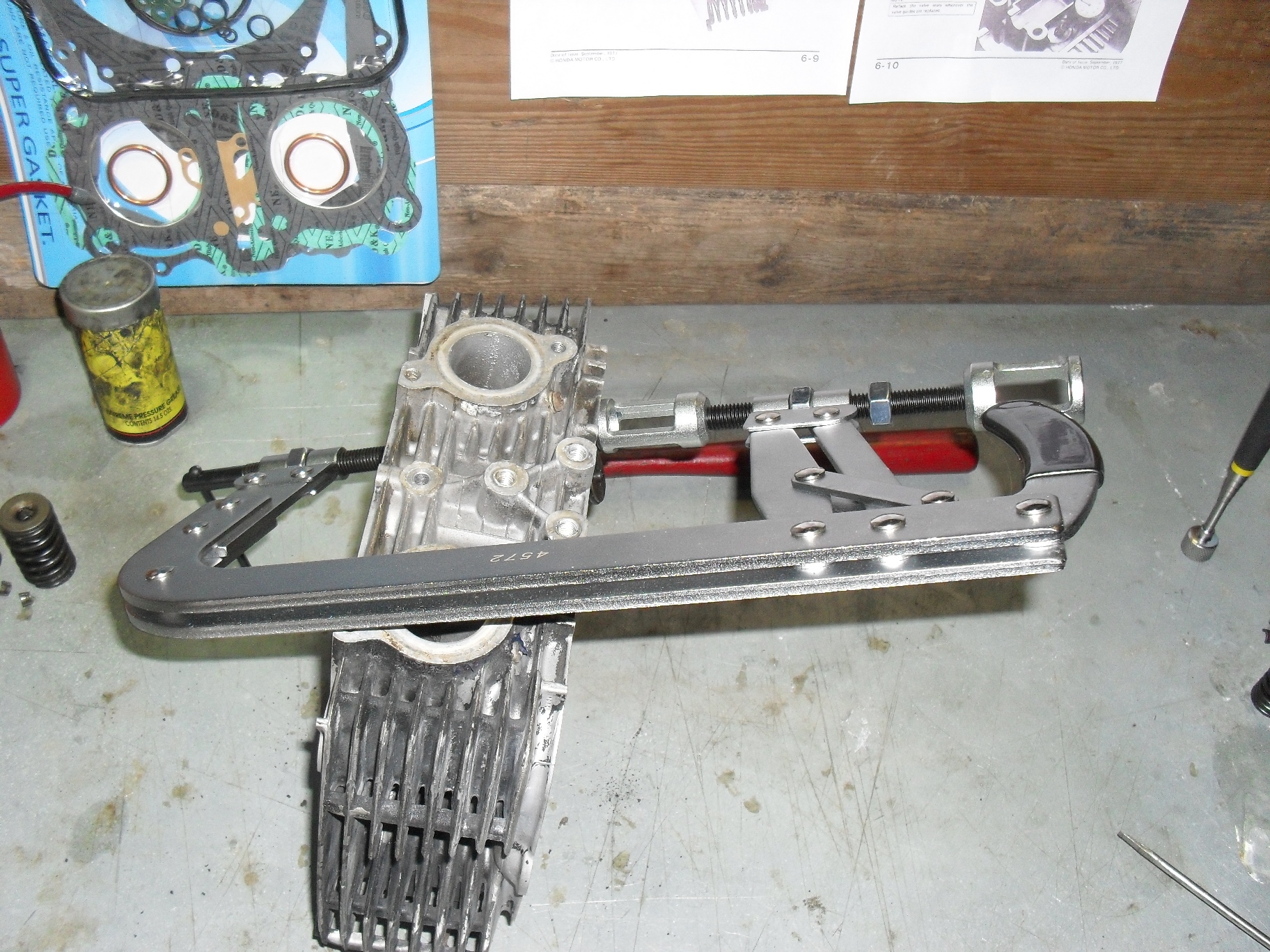
Set your valve spring compressor into place over the first valve you wish to remove and turn the compression screw inward until the spring is compress enough that the valve keepers either fall out or you can reach in with a magnetized screwdriver and pull them out.
It is very important that you keep your valves, springs, & other parts together so that they can be reinstalled in the same opening from which you removed them. This is especially critical for the valves as they wear into their valve guides and seats as the engine is operating. If any of the valves do not come out, or if removal is difficult you may have a bent or seized valve, put everything back together and find a good machinist. The cure for a damaged valve requires replacing the valve & seat as a unit. The valve guide drivers and reamers required for this job are really a bit much to purchase & learn to use for just one head.
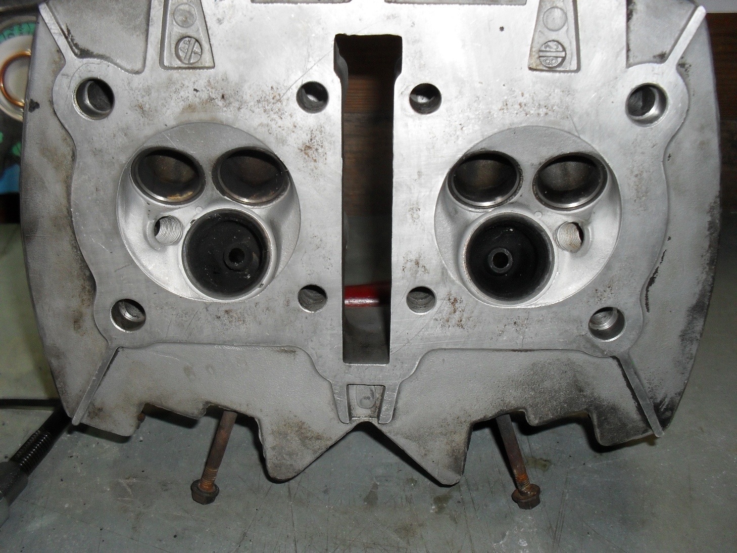
Once you get all the valves out give the head a good visual inspection looking for anything that looks galled, burnt, or cracked
Be sure you check inside the ports to especially around the valve guides. Next check the valve seats which are the hardened steel inserts around the outside of the large holes in the combustion chamber. If any of valve seats 0r guides are burnt, badly scored or pitted , have cracks in them or easily visible excess wear then you need to put it back together & take it to a competent machinist
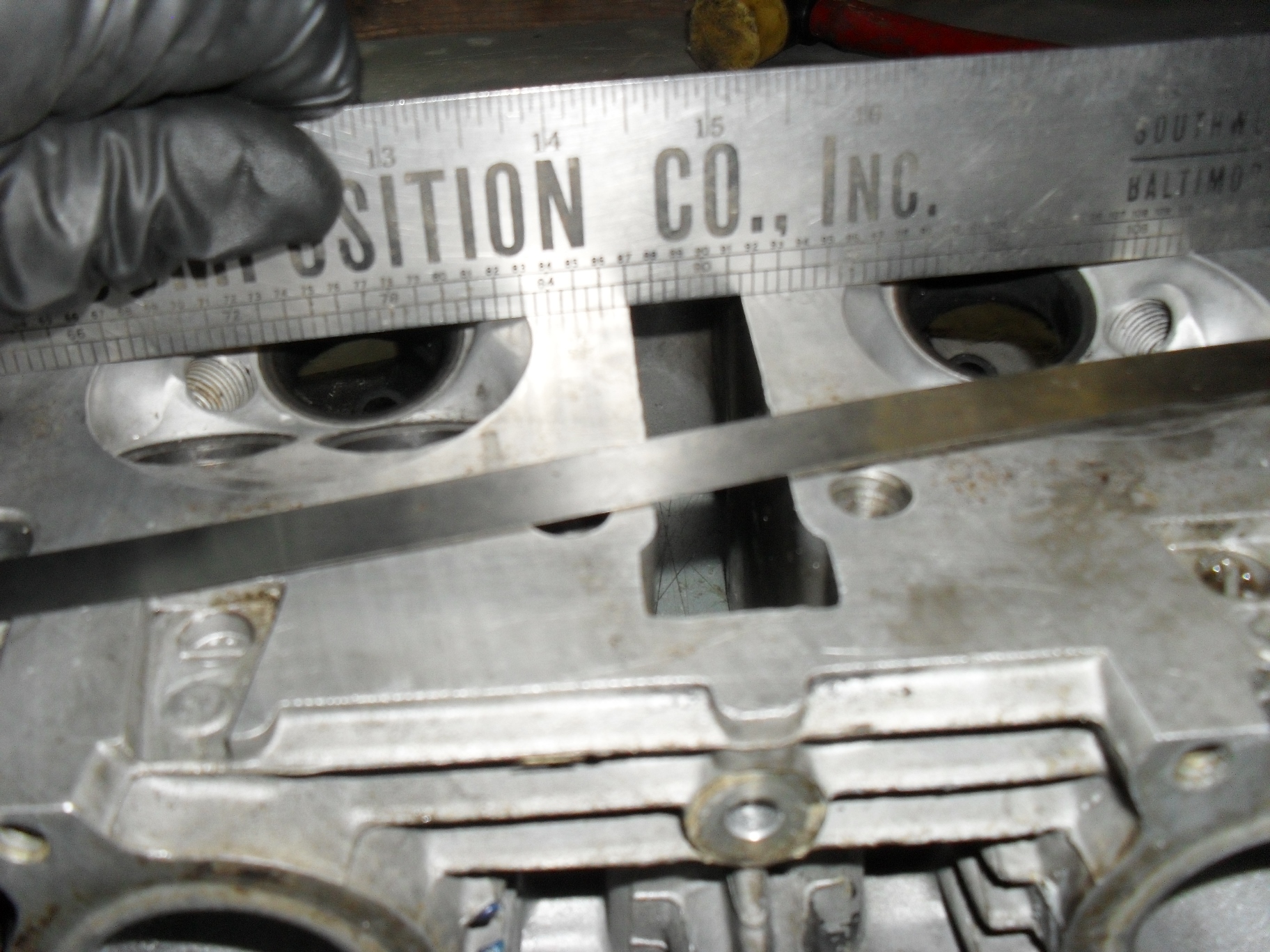
If all looks good make sure the head is not warped beyond acceptable limits. for this you’ll need a good straight edge and a feeler gauge in whatever size your service manual specifies
Place the straightedge firmly across the head in several locations and try to insert the feeler gauge between it and the heads gasket mating surface. If it goes between the two anywhere then a machinist will need to shave the head to level it back out.
Now it’s time to grab the micrometer and check the diameter of every valve stem in several places up & around each one. If any of them are worn beyond the service limit, chances are the valve guides are shot too and this is no longer a normal do it yourself job. Double check them for straightness at this time also,
After that get a caliper and measure the extended length of all of your valve springs. Replace any that do not fall into the specified range for your motorcycle.
Once the inspection process is complete and you are satisfied that all of your parts are in good condition & can be reused go ahead & clean the valves & guides thoroughly. Most of the time you can just scrub the intake valves clean in the parts washer, but the exhaust valves usually have a hardened scale stuck to them so I use a brass wire brush to clean them with. For the valve guides I use a gun cleaning brush, but any small round brush with plastic or brass bristles that fits through them will do. I try to avoid using brushes with steel or stainless steel bristles on parts like these because I only want to remove the grease, carbon, and scale without affecting the base metal.
Pick out whichever valve you want to start with and put a small amount of valve grinding compound around the head of the valve on the surface that contacts the valve seat in the head, and place that valve back into the hole that it was originally removed from. Grab the valve lapping tool & stick one of the suction cups on it to the valve like this and then rotate it back & forth to clean the mating surface. The most efficient way to do this is to hold the lapping stick between your palms and pretend you are trying to start a fire with it. Stop occasionally to check on your progress and replenish the lapping compound if needed. I use a coarse compound to start with & then switch to fine grit, but it is possible to make do with just the fine grit if that is what you have.
Stop and inspect rather frequently, you are not trying the grind the entire surface of the valve & seat flat. What you want is a uniform,well polished shiny ring all the way around the valve & seat at the point where the two meet. Once you have that, to keep polishing is just putting unnecessary wear on your engine parts. It should only take you a few minutes per valve to accomplish this, so keep going until you have all of the valves done.
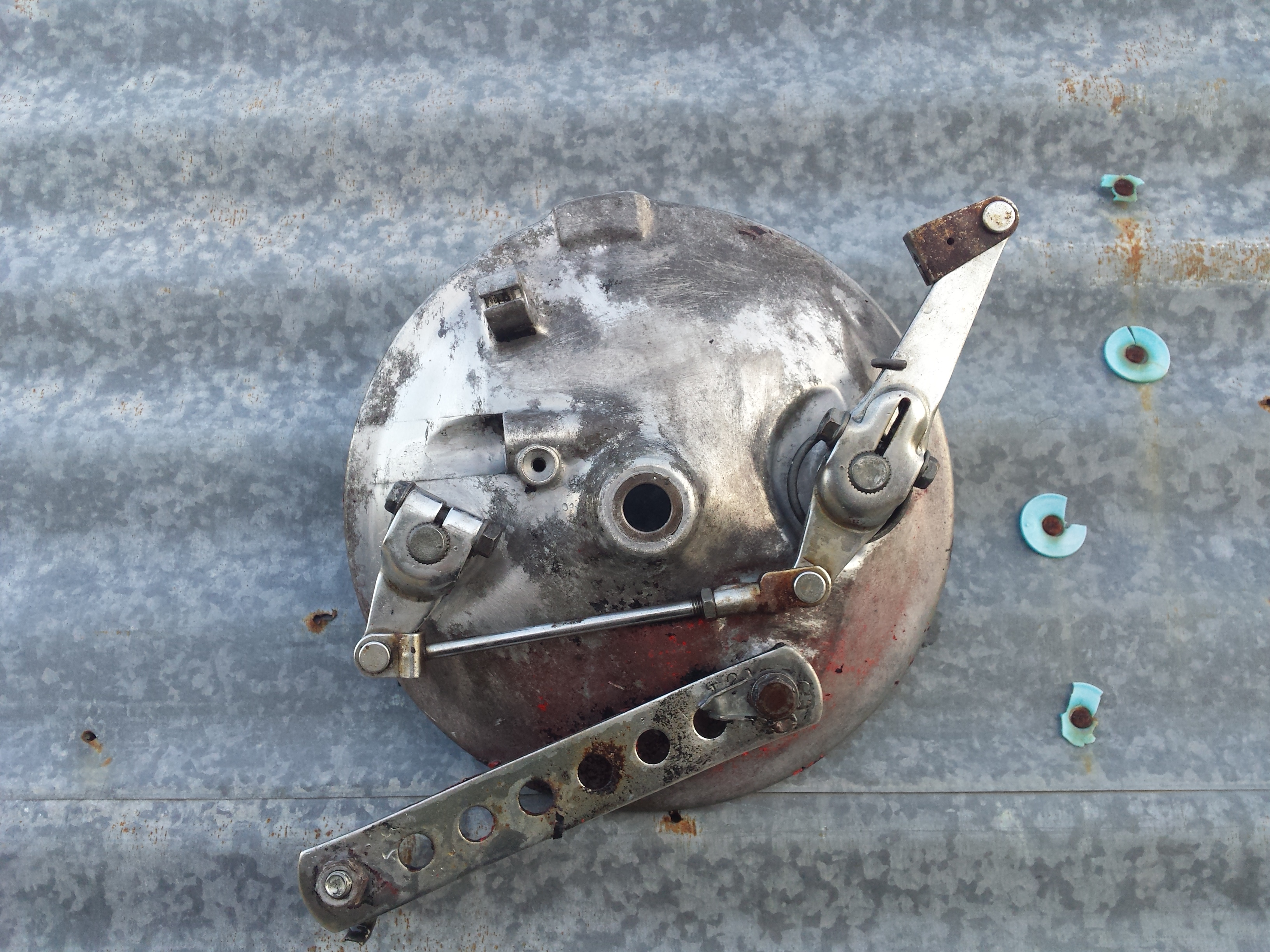
With all of the valves lapped you now need to wash them and the head again and completely remove all of the valve grinding compound so that it doesn’t make its way into your freshly overhauled engine and grind up parts that don’t need it. Then open up your gasket set and find the valve seals. I have the seals for this engine laid out above.
The two larger one are for the exhaust valves and the four smaller ones are for the intake valves.
Once you have all of the seals into place it is time to start reinstalling the valves remembering to put each valve back into the hole that you removed it from to start with. First push the valve back into the hole.
It should go in smoothly, make sure that it doesn’t push the new seal off of the valve guide. Put the matching valve spring(s) and retainer back into place over the valve stem.
You will have to carefully hold the retainer while you put the valve spring compressor into place to compress the valve spring(s).
Compress the springs until you can see the grooves for the valve keepers well enough to reinstall the keepers.
Put a thick coat of grease on each retainer to stick it to the valve stem when you put it into place.
If at all possible use a pair of tweezers or needle nose pliers to put the keepers on the valve stem. If you find that you must use your fingers to get them both into place be extremely careful and make sure that the compressor is securely clamped and not going to suddenly pop loose and crush your fingers while you are positioning the keepers. You have been warned.
When you have the keepers in place on the valve stem then slowly unscrew the clamping screw and if necessary keep the springs and retainer straight as you release the pressure. Remember if your compressor has a release handle on it like mine does, do not use it to clamp & release the valve springs. Always use the clamp screw. The release handle is there to allow you to move it from one valve to another without having to fully unscrew the clamp every time. When you have fully released the pressure & moved the clamp your vale should look like the picture below with both keepers trapped securely between the retainer & the valve holding the whole lot securely together.
Repeat these steps until all of your valves are securely reinstalled in the head.
I have tried to be as honest as possible with you about the possible pitfalls and risks of D.I.Y. motorcycle head service, but if you are willing to take your time, check everything carefully, and work in a meticulous fashion there’s no reason that you cannot give it a shot. Just be willing to take the risk of trying on your next restoration or overhaul and you’ll find yourself having that much more satisfaction with your handiwork once the engine is up and running.
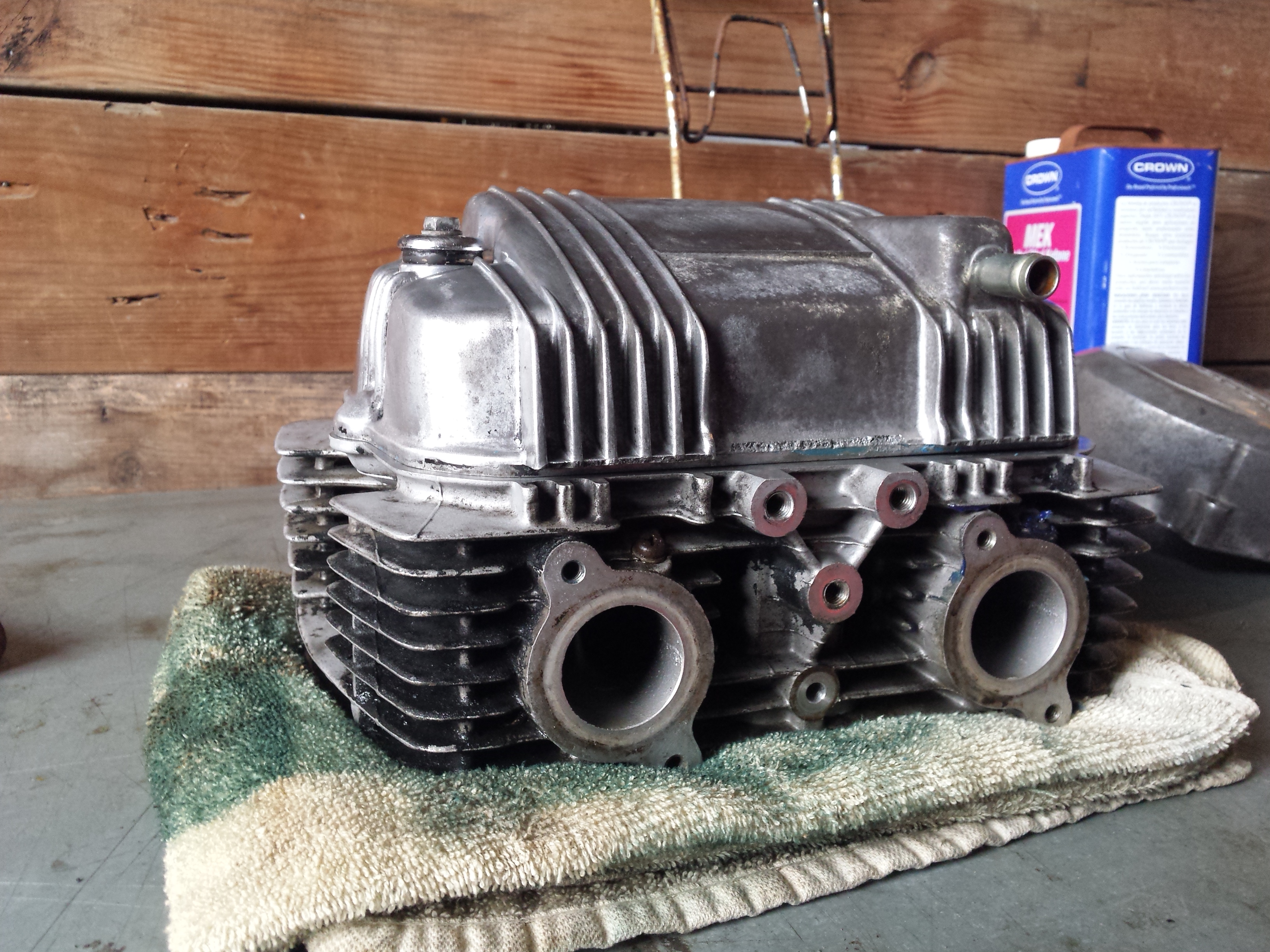
Of course since I want this one to look as good as it works I covered up all of the mating surfaces & plugged all the ports before spraying my favorite ceramic filled engine paint on it. If you need tools and supplies just visit my webstore’s tool sections and search for what you need. If you can’t find something there let me know & I will point you in the right direction even if it means sending you to someone else.
Today I’m going to show you how to perform a Honda CM400 valve adjustment. This basic procedure covers 1978-81 CM & CB400T Honda twins. This engine is from a 1980 CM400. Please refer to a proper CB/CM400 service manual to verify the exact procedures & specifications for your motorcycle. I will give the valve lash & misc. other tune up specs at the bottom of the page.
Gather up the tools you will need along with a copy of the appropriate service manual. Please note that it is not necessary to remove the engine from the motorcycle to perform this procedure, I already have this engine out so that I could do some some fabrication work & painting to the frame. This is the long delayed Project wAmmo bobber that I should have finished months ago, but now I am back on it with a vengeance. You will need to remove the fuel tank, gear shifter, and whatever other parts are necessary so that you can remove the valve cover & the left side crankcase cover. Once all of that is done then remove both sparkplugs.
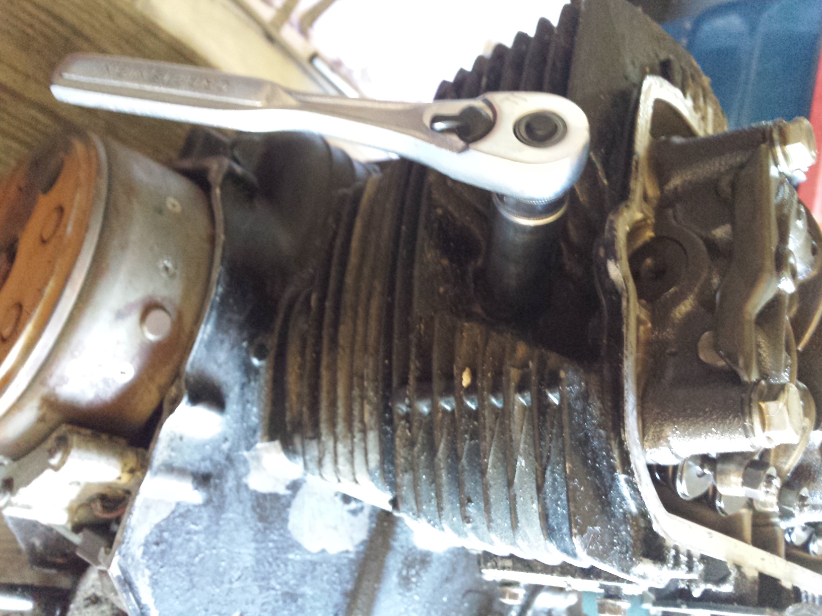
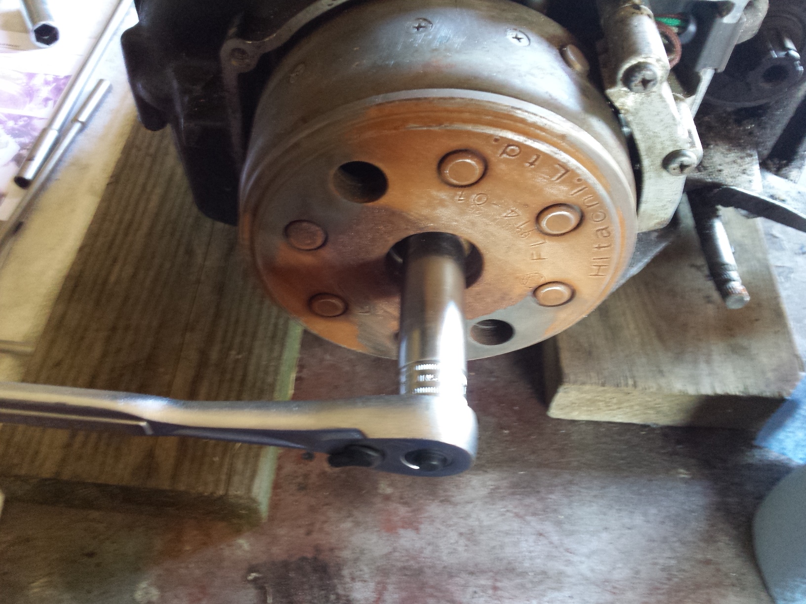
After you remove the spark plugs, switch sockets & turn the engine in the direction indicated by the arrow on the alternator rotor. The big rusty flywheel looking thingy you see in these pictures for those of you who have never seen one before. This one had to have some of the rust sanded off so that I could see the markings on it.
Turn the engine and watch for the intake valve rocker arm on the side you are adjusting to move down and then back up. These little Honda twins have a 3 valve per cylinder layout with 2 intake valves & 1 exhaust valve per cylinder.
Once the intake rocker arm returns to the top continue to turn the engine slowly and line up the next “T” mark on the flywheel with the pointer on the engine case, as it comes around. If the exhaust rocker arm starts to move you have gone to far & must circle the engine all the way back around & start over. Do not turn the engine backwards to get to the timing mark if you miss it.
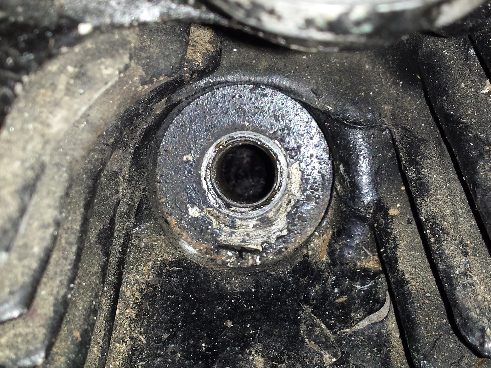
Then verify that the piston is indeed at top dead center. On this engine it is fairly easy to do just by looking into the spark plug hole.
With the piston at top dead center for the cylinder you are adjusting both the intake & exhaust valves should a little bit of play in them unless the engine has severe wear or improper maintenance that has caused valve recession which will close up the gap. Too much lash is also detrimental to your engines performance and will cause your engine to tap very loudly. Too little lash will eventually lead to a burned valve if it doesn’t close completely.
Loosen up the lock nut for whichever adjuster you choose to start with, here I am starting on the exhaust side.
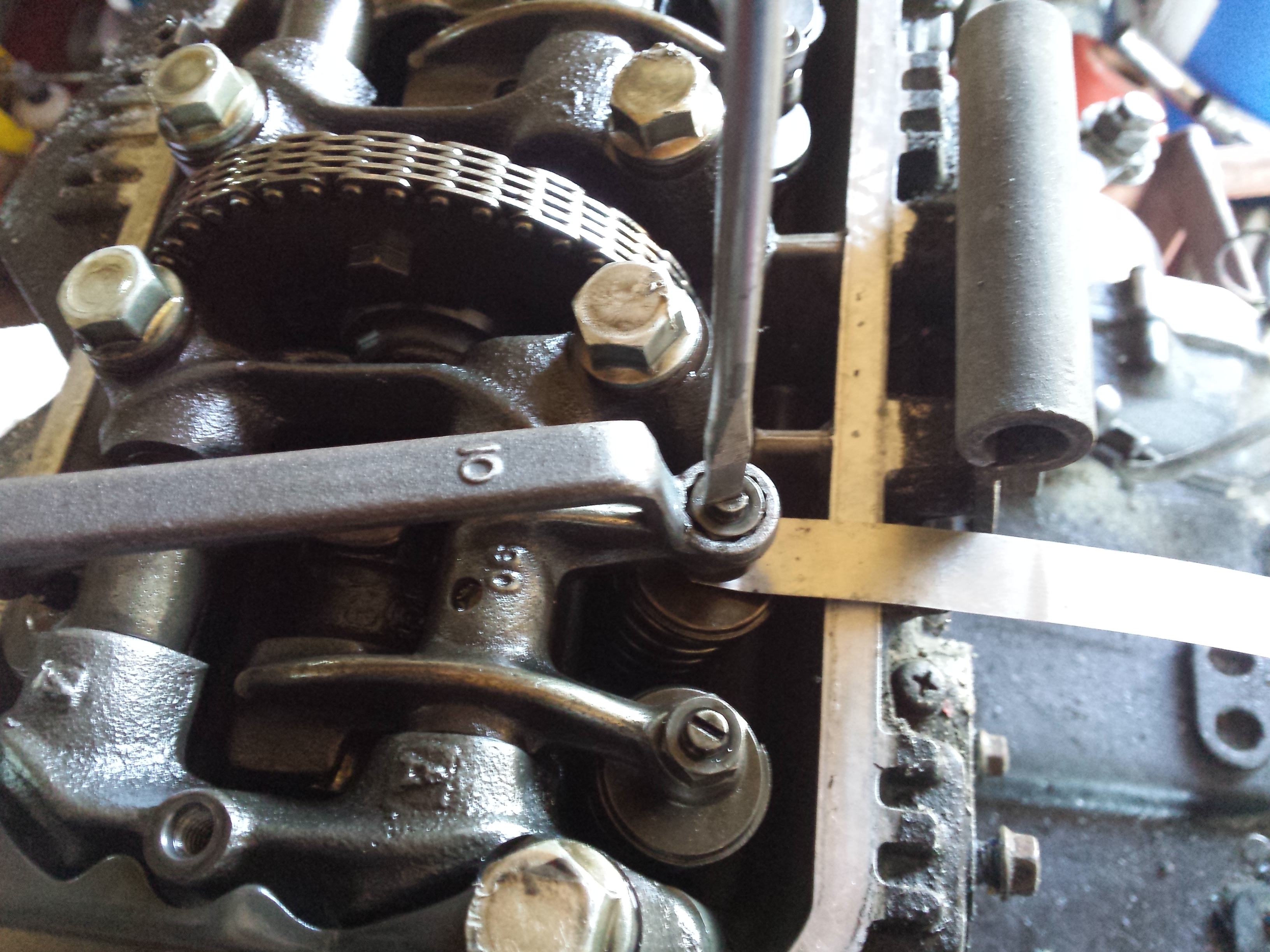
Then insert the proper size feeler gauge, loosening the adjuster with a flat screwdriver if needed.
Then carefully tighten the adjuster screw & lock nut until the feeler gauge is able to be removed & re-inserted with just a little bit of drag, but the next size larger feeler gauge should not fit. It will be necessary to hold the adjuster screw with the screwdriver as shown below while you are tightening the lock nut. Be sure to recheck your lash after you tighten down the lock nut for good, sometimes you may have to readjust to compensate for the adjustment screw moving when you torque the lock nuts.
Once you have all of the valves adjusted properly replace the engine covers being sure to inspect & replace all gaskets & seals as needed.
Valve lash and some miscellaneous tune up specs are below:
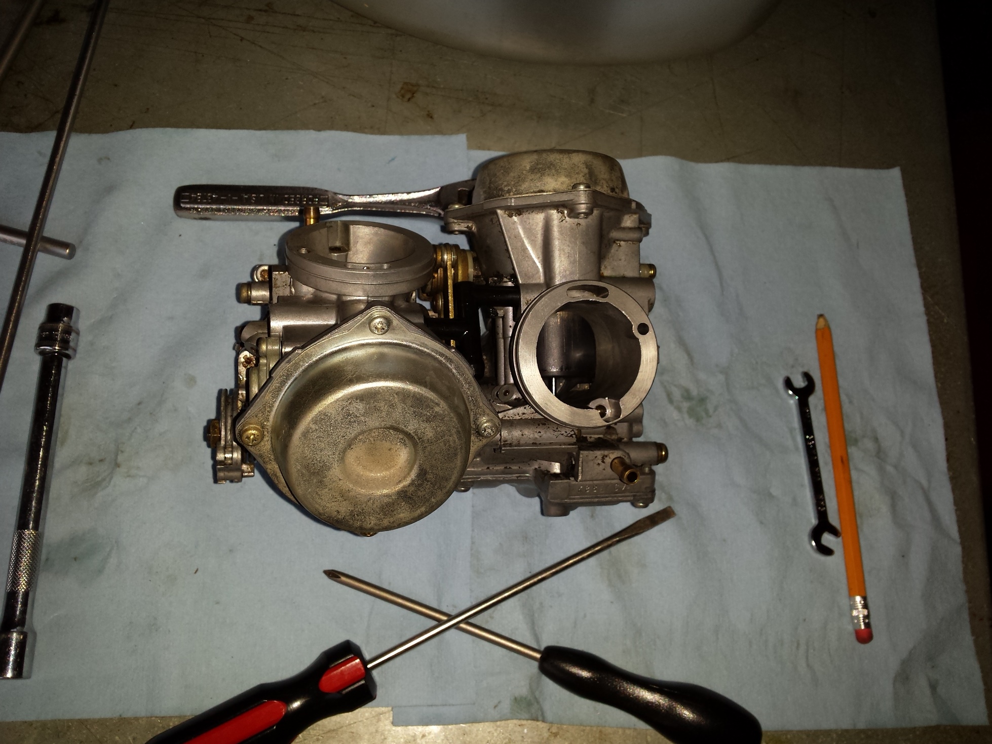
In the last installment, I had removed this set of carburetors from a 97 Honda Shadow 1100, after washing all of the loose crud from the exterior it was time to begin dis-assembly. This is not going to be a full on complete step by step tutorial, but we will cover all of the highlights that are specific to this job. Here you can see that the float bowl is off and although the interior of this carb does not look that bad there is a thin film of of fuel varnish on all the surfaces so I definitely going to clean that out.
Don’t forget, that if you need to you can enlarge any picture on this blog by clicking on it.
As always when working with multiple carburetors, it is best to dis-assemble one at the time and to lay the parts out in a reasonably orderly fashion so that you can reinstall the parts back into the carb body that you removed them from. Below you can see the float bowl, float, jets, etc. are lying on the table and I’ve removed the top and am about to pull out the spring and slide.
Since my ultrasonic cleaner is small to prevent part mix ups I only put one carbs parts at the time in it. One nice thing about dealing with the Shadow carburetors is that both of the air cut off diaphragms are on the outside of both carb bodies and can be reached without breaking the carbs apart, this makes it much easier to clean those critical passages.
Now it’s time to begin the modifications that will really wake your old Honda up and make it sing a new song of power and glory! You should wash the slides off good and inspect the diaphragms for holes, or rips, if you find any problems you will need to replace the diaphragm before proceeding but if all is well, look insde at the retainer and using either a proper JIS screwdriver or an 8mm socket twist the retainer counter clockwise about 1/4 of a turn until it pops loose and will fall out, remove the needle (aka the metering rod) being sure to note if there damage to the retainer or it’s spring.
The Dynojet Research needles are packaged as shown, refer to the instructions in your jet kit for assembly instructions to match your particular application.
Here’s a quick shot of the slide, retainer & jet needle.
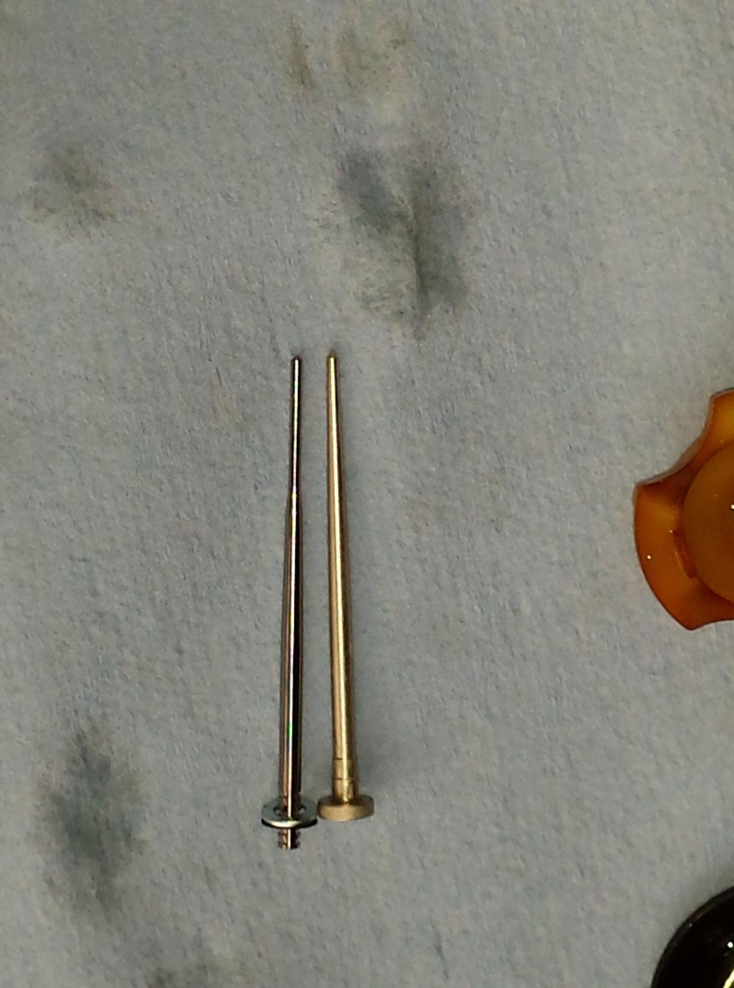
The next picture down is a comparison of the shape of the stock needle to a Dynojet needle. This difference in shape makes enough of a difference in flow that it should be used with the matching jets supplied in the kit. Likewise you can’t use your leftover kit jets in another bike without purchasing the correct needles.
The stock Honda needle is on top and the Dynojet needle is below it.
To simplify reinstalling the needle first insert it along with any spacers into the slide, then place the retainer into the end of an 8mm socket like this and then turn the slide upside down
while holding onto the needle as shown in the following picture andinsert the retainer into place and turning it to the locked position.
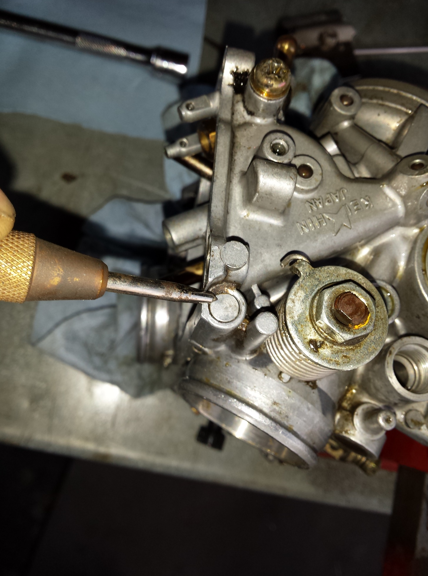
Before I finish cleaning the bodies the idle mixture screws need to be removed. They are located under these caps on the sides of the carburetors. If you live in a state that requires visual emissions equipment inspection you should purchase new caps when you buy your carb kits or your bike will fail inspection if it does not have these caps on it.
Centerpunch the holes and the very carefully drill through the caps stopping as soon as the drill bit breaks through the caps so you do not damage your carbs.
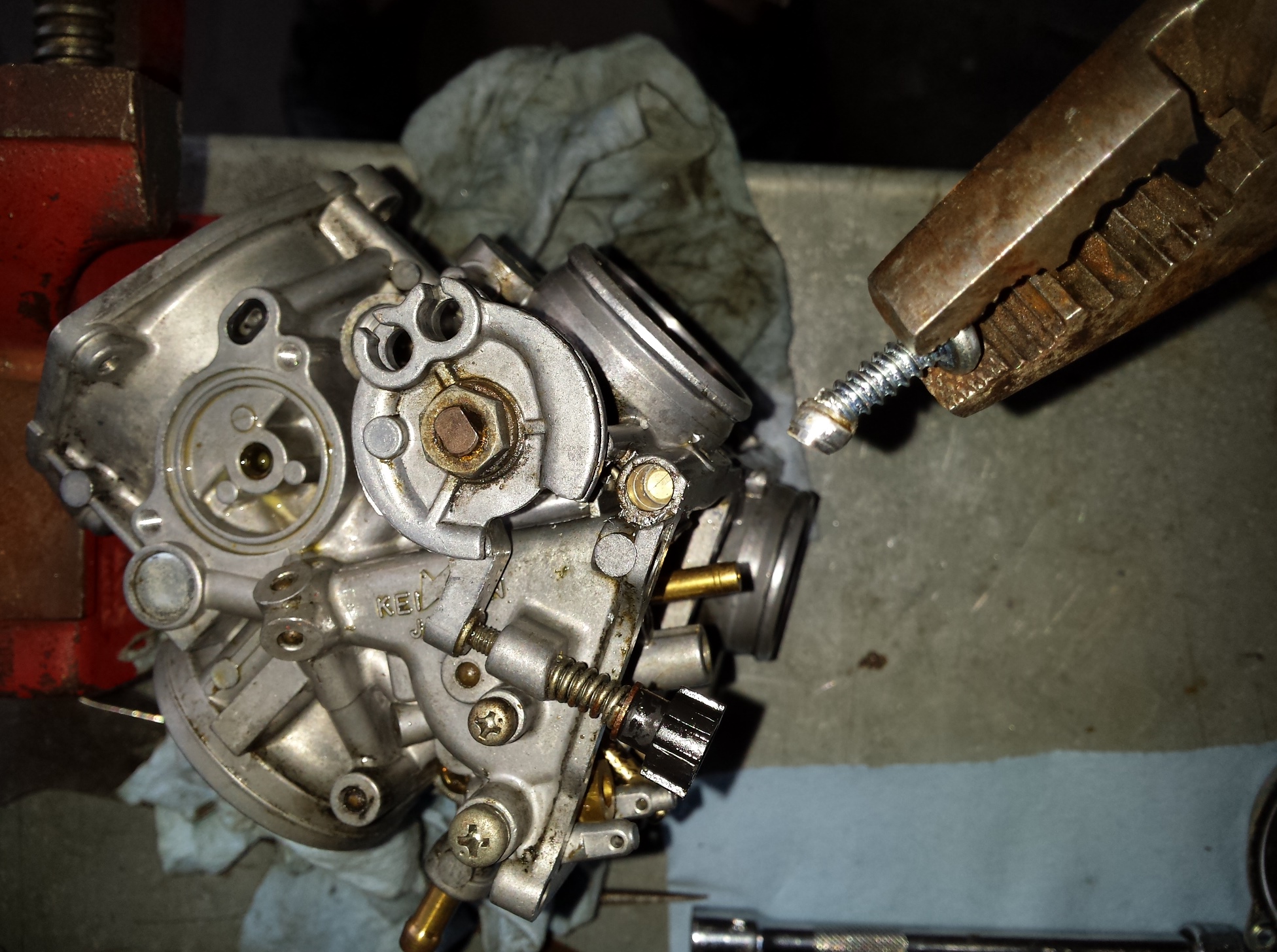
Then you a sheet metal screw of the right size (supplied in the Dynojet kit as is the drill bit) and screw it into the hole far enough to get a good grip on it & then
yank it out with a pair of pliers. If you are just installing the jet kit without cleaning the carburetor turn the screws all the way in until seated and then back out 3 turns for your initial setting. If your are cleaning the carbs as I am here carefully remove the mixture screws, their springs, washers and o-rings and then thoroughly clean the carb bodies.
In this shot below things are going back together now, just reverse the diss-assembly process checking all of your parts,float height, gaskets etc. and correcting any problems you find.
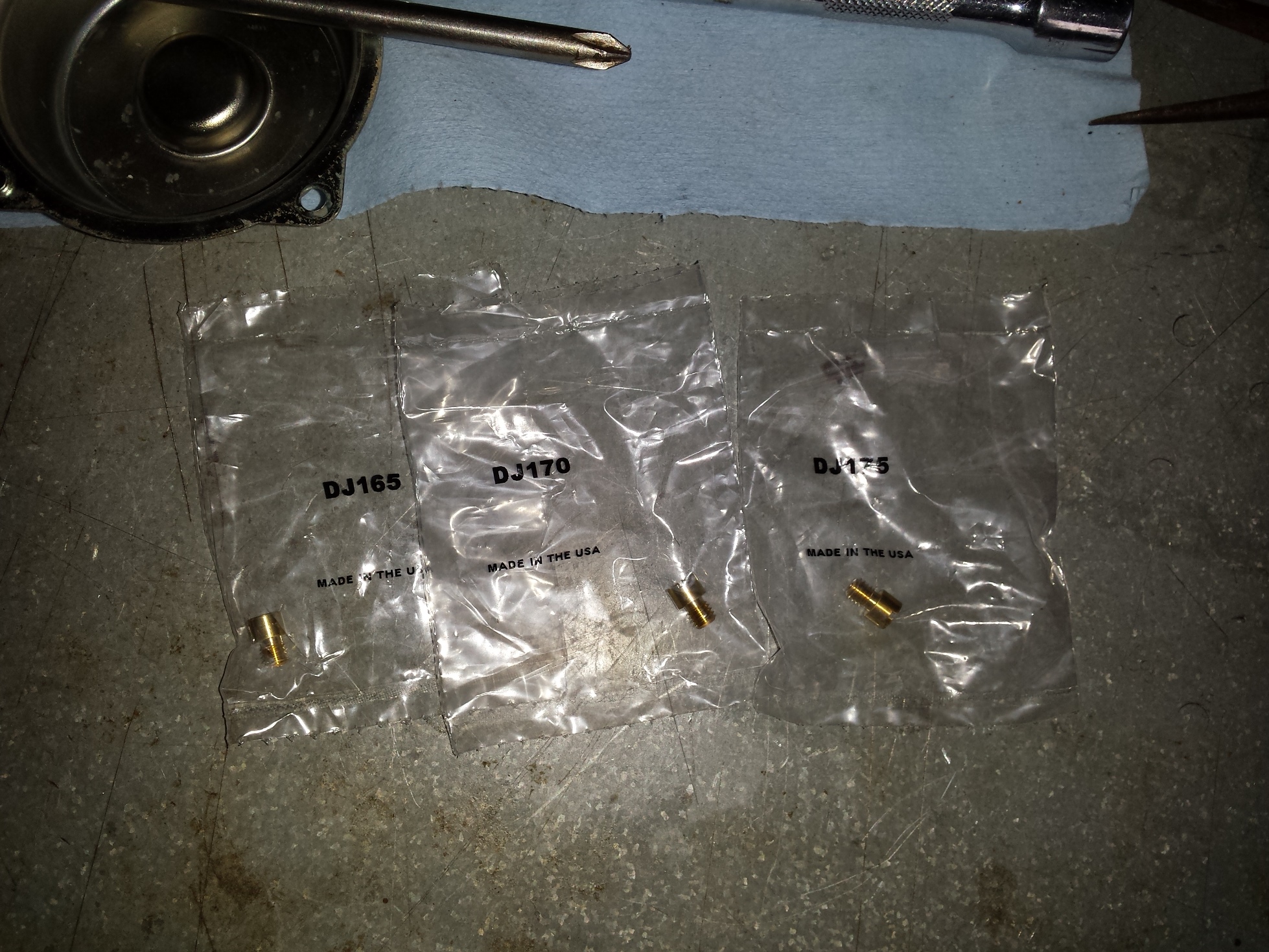
When it is time to put in the main jet you have a decision to make based upon the modification level of your motorcycle. Since this particular bike had a pair of large tube drag pipes on it, I went ahead & put the largest jets in the kit in it. Don’t just automatically put the biggest jets in especially if you are running stock or quite aftermarket pipes and the factory air filter setup.
You should also be prepared to do a bit of tweaking especially to the idle mixture screws to get a good idle with a good throttle response as you come off idle. One must also be prepared if necessary to pull the carburetors completely back out if need be to try a different set of jets or alter the jet needle cir-clip position for the best running. If you pay attention to the instructions in the kit this is not likely but it is a possibility.
There you have it, if you’re contemplating doing this to your bike at home first make sure that it is running well, and that it has new plugs, and that the ignition and charging systems are up to spec, and that there are no other problems such as cracked intake boots that would cause you to have drivability issues. If you put a jet kit in a motorcycle that is not running right to start with, you are very likely to have a motorcycle with a jet kit in it that still does not run right.
Just take your time, read the directions, and keep everything as clean as possible and you should be able to make your old Shadow run & sound even better than it does now.
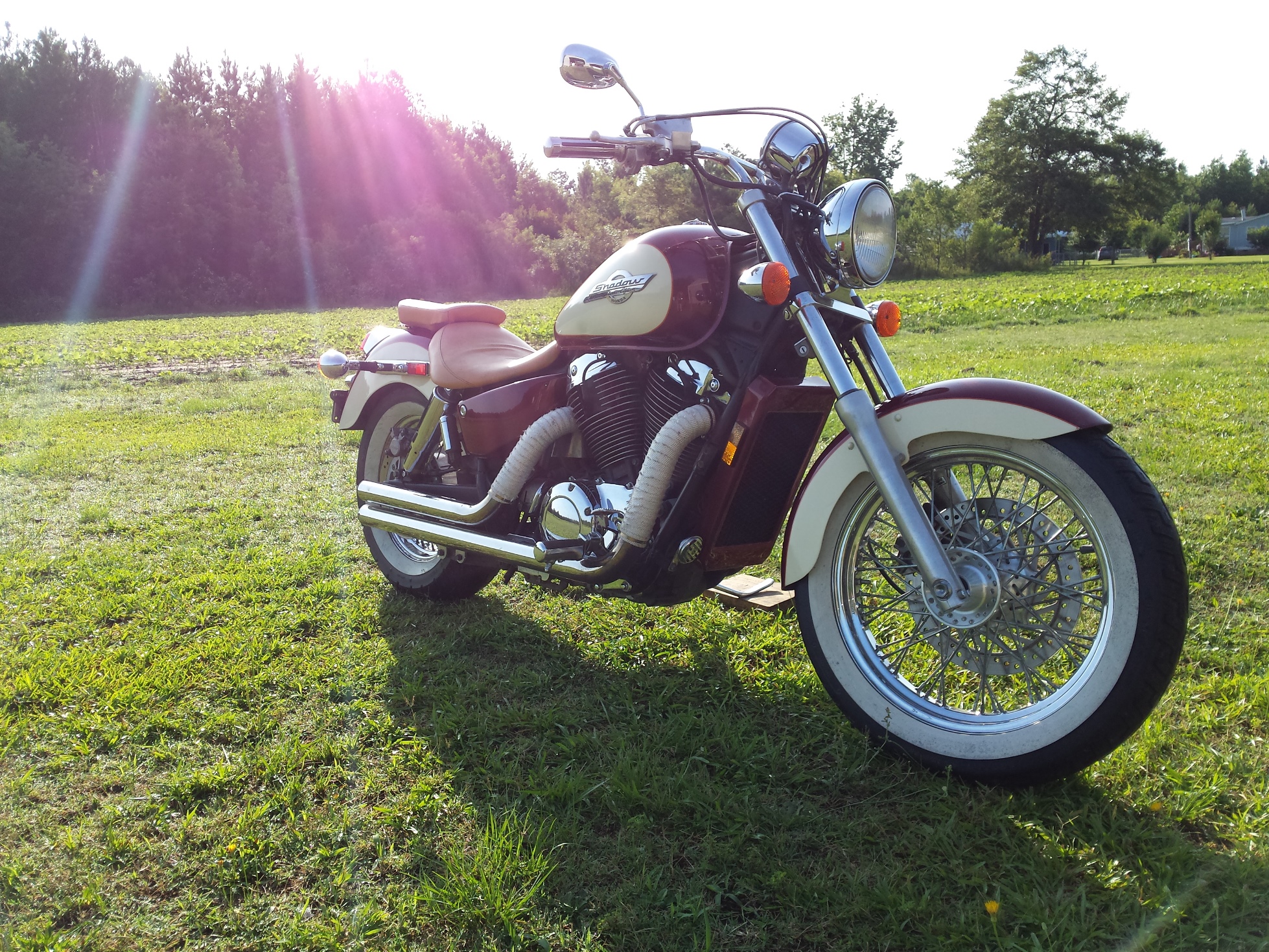
Let’s jump into another “how to” post! Above is today’s patient a 1997 Honda Shadow, a great riding 1100cc v-twin that while still running very well, needed a little tweaking. These motorcycles came from the factory with the carburetors set up toward the lean end of the spectrum for emissions reasons. This led to some drivability issues on some of them, when you combine the original lean jetting with a set of drag pipes, and 17 years of ethanol contamination it was running mighty lean indeed. The engine had a tendency to run hot, hesitate on acceleration, and frequent backfiring on deceleration. So I am going to pull the carbs off, clean them up a bit and install a Dynojet Research jet kit in them. To hear what this bike sounds like before the carb tuning click here go to my youtube channel.
First get the bolt out of the rear of the passenger seat.
Then remove the 2 from beneath the drivers seat one on either side
Lift it up and set it out of the way.
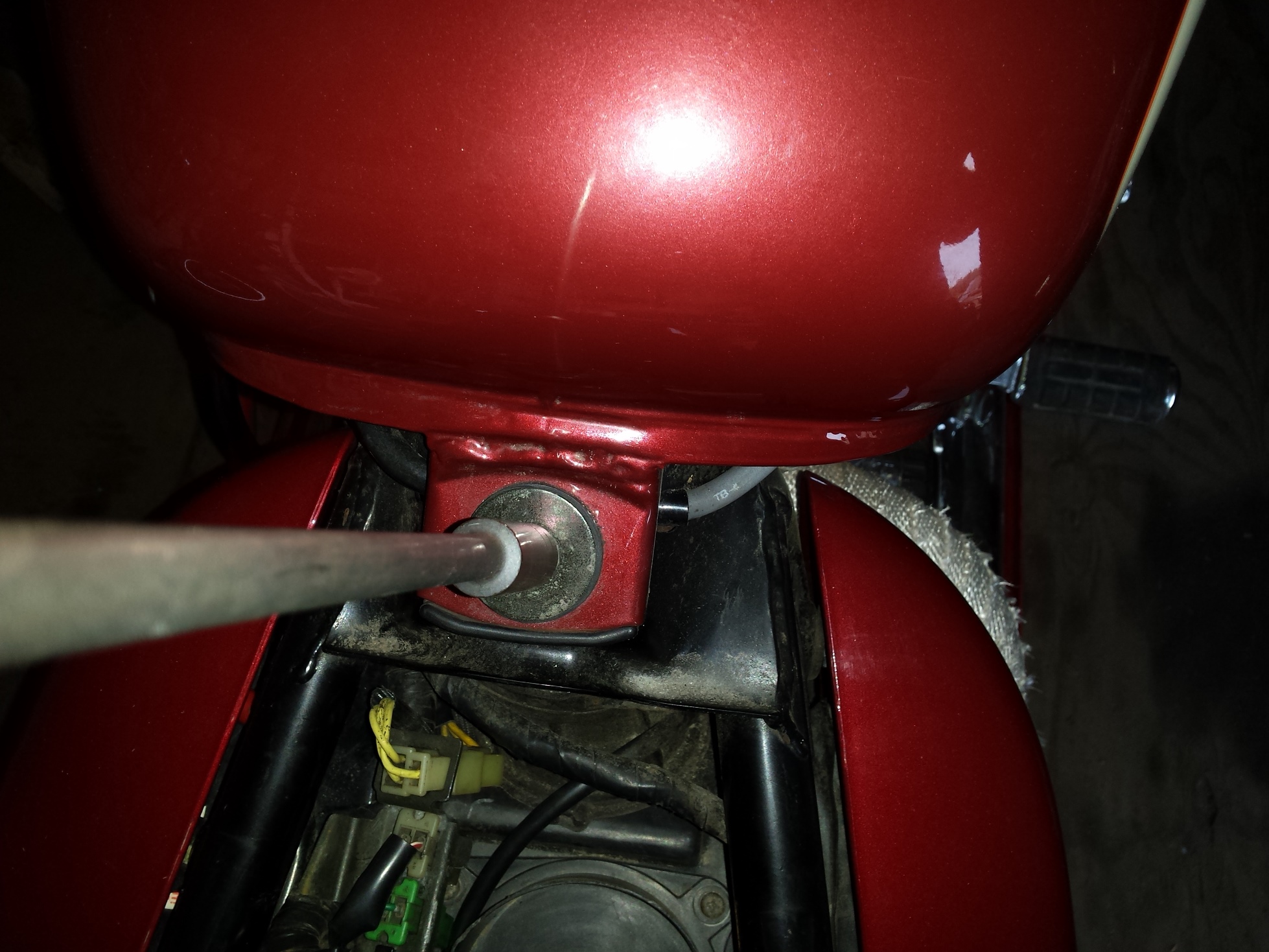
Locate the petcock and shut off the fuel.
Remove the bolt at the rear of the tank,
and the other one at the front of the tank.
Disconnect the fuel line from the petcock.
afterwards lift the tank high enough to remove this vent hose from the bottom
After you have removed the gas tank and placed it in a safe location this is what you should see.
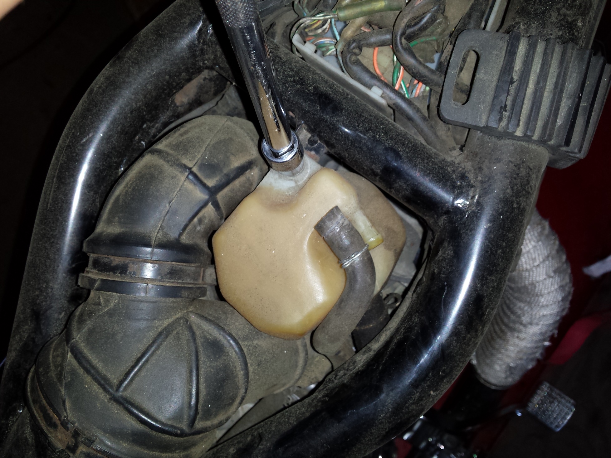
The yellow plastic container is there to catch any oil that happens to emanate from the crankcase ventilation system, so unbolt it,
pull the hoses loose, and set it out of the way.
Next loosen the hose clamps on the rubber piping that leads from the frame to the inlet of the carburetors.
Now we can finally see the carbs!
Time to remove the throttle cables, remove the 2 screws (indicated by arrows) and you will be able to get the cables out of the pulley on the end of the butterfly shaft.
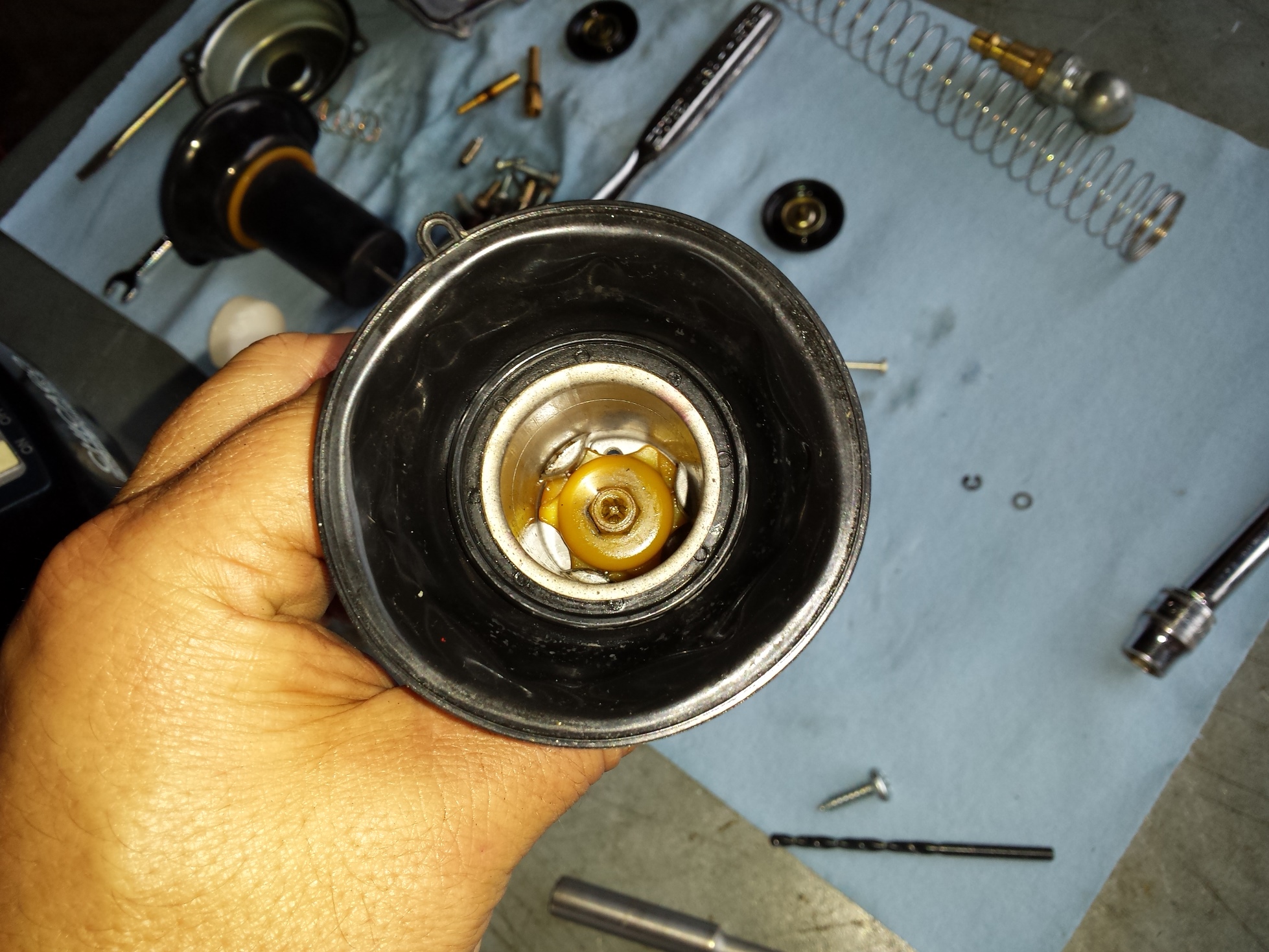
The cold start enrichener is next. These 2 little plungers take the place of choke flaps on the most of the last production carbureted motorcycles. Instead of blocking the air they just add more gas. It works well but is a bit more aggravating to remove. I used to have a special home made tool for getting these out but it has been at least 10 years since I saw it last so I just you whatever combination of open wrench & needle nose pliers that allows me to remove & reinstall them without boogering them up.
Here I am holding one of the enrichment plungers so you can see what it looks like on the inside.
Go around to the right side of the bike and pull the hoses in this tee junction that was connected to the crankcase vent reservoir and fold them back out of the way.
The rear spark plug wire runs through a loom that is attached to the right carburetor so remove it and the enrichener on this side.
You can reach under the carbs now & loosen the clamps holding the carbs to the spigots.
With a rocking and twisting motion you should be able to pop the carburetors loose, but dont rush to pull them up out of the frame just yet.
Before you try to pull them all the way out remove all of the fuel lines and vent hoses, being sure to note which hose goes to which barb.
These carbs come out of the top, just tilt them up sideways and turn them as needed, this is actually much easier than most Japanese cruisers of the same time period that require you to remove the carbs from the side.
Here are the carbs sitting on the workbench ready for cleaning. The next step is into the parts washer to get all of the exterior crud off for dis-assembly.
Keep checking back as I will be posting part 2 of this series very soon.
A couple of weeks ago I promised to do an article about motorcycles and fuel economy, since it does seem to be popular subject people are searching for more information about. There are many things to consider, but perhaps the biggest single key to getting the most fuel economy is to start with the right motorcycle. For the sake of this article we are not going to be considering anything not capable of running at least 60 mph thereby completely eliminating all of the “moped” class machines. Although if you live in a city and do a lot of driving in areas with low speed limits you may still wish to consider one.
This is by no means meant to be a complete listing. Your mileage may vary etc. There may be many similar or equal machines to the ones that I have named below so don’t beat me up if I left out your favorite. Please note figures given are gleaned from EPA ratings, personal experience, and/or reliable motorcycle data websites, and apply only to well maintained factory stock machines.
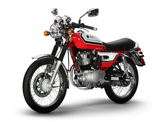
Sym Wolf Classic 85 mpg
The smallest machine that I looked at for this article was the Sym Wolf 150, a great looking little machine. Light & nimble it is the smallest motorcycle I would consider for street duty, other than the CB125 that the Wolf is a direct descendant of. Rated at 85 mpg it has great fuel economy, but has a top speed of around 65 mph, and being a very small light machine without much load capacity, I’d recommend you stay off the freeway with this one.
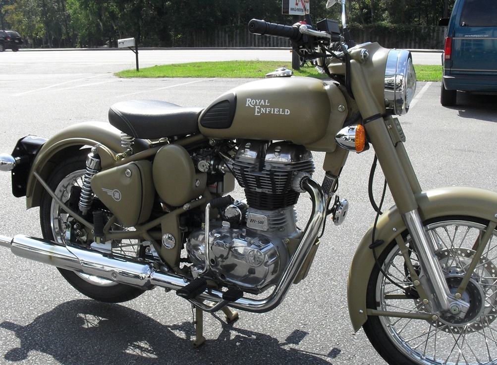
Royal Enfield Classic 500 85mpg
Surprisingly enough the next motorcycle up in the mpg sweepstakes is a heavy solid steel piece of spiritually British iron. Built in India for several decades, the Royal Enfield 500 has gradually evolved from a clunky unreliable relic, into a machine with a reasonably modern fuel injected engine slotted into a chassis that is still a relic, but in a good way. 27 hp combined with heavy construction isn’t going to win any drag races but the 85 mpg is astounding in a machine with enough torque for passenger hauling, and with an 80+ mph top speed you can still get on the freeway and go places. I probably wouldn’t keep it pegged WFO for hours on end but it is still capable of interstate travel at a relaxed pace.
CCW Tha Heist 80mpg
Next in the range are the 250 class retro & cruiser bikes such as the CCW’s Tha Misfit & Tha Heist, the evergreen Honda Rebel and Suzuki TU250 fit this group as well. These are decent little machines that are capable of up to 80 mpg. Extensive Freeway duty is a bit questionable on any of them but they are definitely a step up from the smaller Wolf. If you gotta travel the high speed roads you should probably look at the Japanese offerings first. The CCW bikes are great looking though and they do have a catalog of hop up parts to get more speed out of them but that will probably diminish fuel mileage.
A small step down in fuel economy but a huge step up in performance is the 250-300cc sport bikes such as the Kawasaki Ninja & Honda CBR. The baby Ninja can get just a tiny bit past the ton in bone stock condition even with a fat boy like me on it, and while I haven’t ridden the CBR250 yet, all the magazine testers put its top speed around 97 mph. The best part is that both of these bikes are as reliable as anvils, more than capable of traveling anywhere you want to go at any legal speed without ever breaking a sweat. Being fast enough to beat most cars at the stoplight drag races is also a very comforting safety feature as well. These bikes are capable of 70 mpg when ridden conservatively and still knock down over 55 mpg when you ride the snot out of them.
Honda NC700X 64mpg
I have consciously tried to avoid singling out any one machine for praise, especially one that I have not ridden yet, but the Honda NC 700 X is rated at a very good 64 mpg. This is a full size 700cc adventure touring type machine capable of cross country touring on any road of your choice. Compare that to a big scooter such as Honda’s own Forza with its streamlined bodywork and 300cc engine that only gets about 4 mpg more.
There is a huge range of motorcycles that slot into the 45-55 mpg range. Harley Sportsters, FXRs, etc., most cruisers, vintage bikes in the 350-850cc range. Practically every 600cc sportbike made by anyone can get 50 mpg+ and provide amazing performance. Even some of the 900-1000cc bikes can do 45 mpg. At this range the cars are starting to catch up mpg wise but these are incredibly slow & boring cars that get this kind of fuel mileage.
It only gets 33-39 mpg but does anyone really care?
You don’t really drop below 45 mpg until you get into either hyper sport machines such as the ZX14 Ninja or the Hayabusa, or full dress touring motorcycles like the Gold Wings, K1600 BMW, & Electra-Glides. Even so most of these machines are still capable of 35-45 mpg averages. While they are not economical sounding in motorcycle terms, in the economy of scale against other forms of transport with the same intended mission they are still very reasonable. The big touring machines are incredibly luxurious and loaded down with more amenities today than anyone ever thought possible. To get a performance automobile capable of matching the speed of a box stock big bore sport bike will cost you at least $100,000 and it won’t get anywhere near 30 mpg.
Yes the biggest Harley is rated at 42 mpg combined. Impressive.
As I said at the beginning if fuel mileage is what you are after in a motorcycle, the best way to get it is simply to buy the right motorcycle, maintain it well and ride it in a careful and conservative manner, keeping your speed down as much as safely possible. I’ll come back in a few weeks and touch on some maintenance items that you need to be sure to keep up with to maximize fuel economy, and at a later date will write a post about modifications & driving techniques, to help you wring every last mile out of your dollar.
People keep doing a repeated search for, “four turns out from the seating of fuel screw of keihin 4 stroke carburetor do get more mileage in motorbikes.” The answer to this is no. The mixture screw should be correctly called the idle mixture screw, as it only controls the air/fuel ratio at idle. This screw should only be adjusted as needed to correct the idling of your engine & the very beginning of the transition off of the idle stop. And even then all other factors affecting your engine, such as spark & air should be checked & corrected first. Normally the only reason you would turn the mixture screw out that far, would be on a high performance engine that has been re-jetted for maximum power. Of course an engine like that gets the minimum fuel mileage.
On a stock engine if you turn the mixture screws out 4 turns you will develop drivability problems, and there will be an increased risk of engine failure due to overheating caused by an excessively lean mixture at idle. The other problem is that with the screws that loose is that you run the risk of them vibrating out and leaving you stranded. Plus your gas mileage will probably go down due to the way you have to twist the throttle to compensate for the drivability problems.
Since this is a popular topic amongst those who commute by motorcycle, sometime soon I will do a post on how to maximize fuel economy. Except for basic maintenance none of it will involve any work on the carburetor.