Harley Keihin Carb clean

Another bike left to die


This patient is a 2000 Harley Davidson FXST Softail standard. I realize this isn’t really vintage but it is 19 years old. Picked up not running, coated with a quarter of an inch of dust, 2 flat tires, and a tank full of stale gas it is in dire need of some attention before it’s too late. After making sure it had compression and spark I was ready to tear into the Harley Keihin carb.

Harley Keihin Carb on 2000 Twin Cam Softtail

First thing was to remove the air cleaner than go to the other side of the bike to loosen the enrichment(or choke) knob so you remove it cable and all with the carburetor. After this pop the carburetor out of its spigot.

Harley Keihin Carb on 2000 Twin Cam Softtail

Once you have the carb loose unhook the fuel line and throttle cables.

Harley Keihin Carb

Take the Harley Keihin carb to a work bench where you have plenty of room to spread out the parts as it is disassembled.

Harley Keihin Carb

Harley Keihin Carb

Make note of the numbers on the carburetor as they might come in handy when you need to get parts. Then pull the enrichment plunger out and set it aside.

Harley Keihin Carb

Take the accelerator pump housing, diaphragm & spring off the bottom of the float bowl.

Harley Keihin Carb accelerator pump

If the previous mechanic would have used a top shelf screwdriver like this Vessel Impacta shown here I wouldn’t have had to replace so many of the screws.

Harley Keihin Carb float bowl screw
Yes these are JIS screw

With the float bowl off inspect everything well and make note of what parts are where.

Harley Keihin Carb inside float bowl

There was a little damage on the mixture screw tower from the plug being removed. Normally there’s a cap over this that you have to drill a hole in & use a wood screw to pop it out. If you live in an emissions inspection state the cap has to be replaced with a new one. If I lived in an emissions inspection state this carb body would have to be replaced.

Harley Keihin Carb pilot mixture screw
someones been in here before

first remove the float & float valve, followed by the main jet & emulsion tube.

Harley Keihin Carb

then take out the pilot (idle) jet.

Harley Keihin Carb idle jet

Next up is the idle mixture screw, first screw it all the way in slowly & count how many turns it takes to bottom out, and make a note of it. Then remove the screw completely.

Harley Keihin Carb mixture screw

There are four parts to the mixture screw assembly on a Harley Keihin carb. 1. the screw itself 2. the spring 3. a small washer & 4 the o-ring. Chances are that the o-ring & washer will remain in the carburetor body & you’ll have to use a small pick to carefully fish them out.

Harley Keihin Carb pilot mixture screw parts

Moving on to the top cover remove it,

Harley Keihin Carb top removal

and then set it & the spring off to one side.

Harley Keihin Carb CV diaphragm

Pull the slide out, inspect the needle (metering rod) for wear & check the diaphragm for holes.

Harley Keihin Carb

I always push the needle jet that the metering rod passes through out of the body so I can inspect it too. Since I clean carbs in a heated ultrasonic cleaner if I don’t push it out and keep track of it, it’ll probably fall out any & I’ll have to go fishing for it.

Harley Keihin Carb

Here’s a shot of the float chamber with all of the removable parts out.

Harley Keihin Carb

Since this is only a repair job & not a restoration this carburetor only got a cleaning, no vaporblasting. This body was in nice shape & looks decent with only cleaning. If you’re working on a crusty old pile of junk and want your parts to look good again please see my vaporbasting page.

The next few pictures show this carburetor’s parts laid out in the order that that they go back in. Make sure you carefully inspect all parts and replace any that are not usable especially the rubber pieces.

Re-install all of the internal parts,

Harley Keihin Carb jets, float mixture screw & enrichner

and the mixture screw being sure to set it as it was before. If you think it was wrong verify the setting with a good service manual.

Harley Keihin Carb pilot mixture screw assembly

Then set the float height.

Harley Keihin Carb float height

Harley Keihin Carb

Carefully line up the accelerator pump rod through it’s hole in the float bowl & reinstall the bowl. Don’t forget to put the bellows on as shown before the float bowl.

Harley Keihin Carb accel pump linkage

The rest of the accelerator pump arts should be reassembled to the carb now.

Harley Keihin Carb

The last couple of steps are reassembling the needle to the slide making sure to put any spacers that may be present back where they were to start with and then putting the slide back in the body, with the spring & then re-installing the cap.

Harley Keihin Carburetor

Once this is all done it’s time to put the carburetor back on the bike, fire it up and make any needed adjustments. I hope you have found this pictorial overview of a Harley Keihin carb helpful & interesting.

Harley Keihin Carb ready to install

Peace Y’all ‘Psycho

Auxiliary Fuel Tank by Pit Posse

While I was in the process of moving I managed to break the end off of my old auxiliary fuel tank that had served me well for over 20 years. When I went looking for a replacement most of the top name brands were rather expensive starting at $45.99 and going up. At the other extreme were a bunch of smaller unknown brand ones from China or India with decent prices but some long shipping times & unknown quality. As a compromise I settled on this one sold by Pit Posse for 39.99  It came with a decent length of hose & a good quality brass shutoff valve. Let’s be honest here, all of these plastic auxiliary tanks cost more than what they are really worth but comparatively speaking this one is a good deal coming from a U.S. based company. The actual product is still made in China though. I’ve been using this one since June 8th 2018 and am very happy with it.

Auxiliary fuel tank & carburetor synchronization guages on an I.V. Pole
My setup for adjusting carburetors.

You might notice that in the picture above that I have my vacuum gauges and auxiliary fuel tank hanging from an I.V. pole.  If you’re serious about doing carb work on motorcycles & four wheelers you need to get yourself an I.V. pole. It turns out that you can get one pretty dang cheap too, click here to see them starting as low as $23 with free shipping. Well worth every penny.

My sychronizer gauges actually come from Honda and were purchased from the inventory of a shop that went out of business. If you don’t have a set and are thinking of buying some do yourself a favor and get a set vacuum gauges, not the mercury sticks. Of course if you have the money you could go for a Carbtune Pro setup. If my gauges ever quit that’s the one I plan to get.

That’s all for today just thought I’d post a quickie product review and share a couple of tips that you might find useful. Until next time,

Peace Y’all

Loving the Reader Feedback on This Blog

It’s always great to hear from readers about the various things that I’ve written through the years, for example a little over three years ago I wrote a post underscoring the importance of always using a new cotter pin every time you need one. Just a few weeks ago I received an email from a reader who had a near tragic ending and these next few words will be his.

Comment: I just wanted to share a story about why you should always check those cotter pins.

I had just rebuilt a 200cc bike, and after riding 50 miles, the back wheel came off. I broke my clavicle, went to the ER in an ambulance, destroyed my helmet, broke my crankcase, and scraped up fairings and the frame. The towing & impound were expensive too. In the end, this cost me thousands, and I was out for 6 weeks w/ a hurt shoulder.

All this because I rode the bike without a cotter pin.

I’d torqued up the rear nut to spec, and it only took 50 miles for the nut to back out. I never thought it would happen…but it did.

Now you’ve heard from a man who really knows and yes he still rides motorcycles. He asked me to keep his identity completely private so I will, and thank you very much kind sir for sharing this with us. If the rest of you don’t already have one stop right now & get yourself a cotter pin assortment.

Another post that has generated a lot of comments & feedback was the one entitled Vintage Piston Valve Keihin Carburetor Overhaul. If you look at this post without reading the commentary you’re only getting half of the story. Check out the whole page, I learned as much from my readers as they learned from my meager do it yourself post. Of course this leads into my other series of posts Dirt Bike Carburetor 101.

Those of you with CV carbs don’t fret, I have several dozen detailed close up pictures of 2 different style of CV carburetors that I have worked on recently & will be getting a couple of detailed posts going for you about those.

Some of you may be wondering about the Project wAmmo bobber that I had started on. It’s probably the main reason that I have not posted as steadily this month as I should have because the darn thing needs to be finished. But it’s up on it’s wheels and actually went to it’s first show despite needing a few more details to finish it up. I hope to have it all wrapped up in the next 2 weeks for final pictures in the meantime give a listen to this video.


That’s about it for this post if you haven’t already signed up for email notifications please do so using the box below. There’s a lot of great stuff coming up & you don’t want to miss a thing.

Most of all thanks for the reader feedback on this blog.


Honda Recon Stalls Going Uphill

I noticed someone has been searching this site for information on this topic. If you have just done or had work done on your Honda Recon 250 ATV or it has been sitting long enough for mud daubers to nest in it, and it runs well other than the fact that it stalls going uphill then you need to check the upper vent hose on the side of the carburetor that runs up to the steering head area. If this hose gets pinched shut or plugged up it will cause this to happen because the trapped air prevents the float bowl from refilling when the atv is on too steep of an incline to vent through the bottom of the carb. Just find the rubber hose that leads from the left side of the carb as shown below. The other end should be up near the steering head and completely open to the atmosphere. Make sure that it is not routed in such a way that the fuel tank pinches it shut when the tank is re-installed.

<top-engine CARBURETOR HOSES RECON>

<Honda Recon Engine Carbs Vent Hose>

If you are trying to sort out why your Honda Recon stalls going uphill or any other problem you may be having with it I highly recommend a good service manual. If you are doing your own work it will save your ass a lot of trouble.


Vintage Piston Valve Keihin Carburetor Overhaul

Hello again everyone, Lets restore a set of carbs for this old Honda! Yes I had already turned them over one time & popped all of the bowls off and blew them out with some carburetor cleaner and put them back on to test run the old bike & see how it sounded, but it was a running a little lean with the pod air filters, plus I was installing a new exhaust  system and needed to re-jet anyway. But the single best reason I have found to go to this extreme is that there is almost nothing else that will make an old motorcycle run like new again the way a complete carburetor refurbishment will. In fact the only thing better is a new set of carbs, which if you pull your old ones apart & find severe damage or wear to the castings, is your only choice.

Here you see the four carburetors, along with a flathead screwdriver, a JIS screwdriver, a set of mini wrenches and a ratchet with a socket. This is not everything you need to completely disassemble them but it’s a good start. The patient is my own 1980 Honda CB650 Custom with a set of Keihin PD mechanically operated carburetors. Although these a very similar to the piston valve or round slide carbs used on a number vintage motorcycles these do have a few differences from the older ones. This will not be a complete step by step guide to restoring every single piece. If need to learn the basics of carburetor repair I suggest that you start by clicking here.

Instead I will focus on how to disassemble the set of carbs, and point out some of the different features along the way, along with a few tips and tricks to make the job more successful. Please note that successful does not mean easier. This is not rocket science but there are no shortcuts either.

The first step in getting a set of carburetors apart is to remove everything you can from the choke & throttle shafts. Here I am using a JIS screwdriver to remove the choke butterflies. What the heck is a JIS screwdriver you ask? Just click here to find out!

Please note that these screws are often punched from the backside at the factory to spread them out & keep them from coming loose & falling into a running engine. This often makes them a pain in the butt to remove.

Next take the tops off and remove the long screws that connect the slide lifters to the throttle shaft.

Be sure to inspect the shafts for damage like this before you start pulling the unit apart. At some point a previous owner had used a pair of pliers to move a sticky slide. To avoid damage to the bushings etc. use a strip of sand paper or emery cloth to remove anything you find like this prior to dis-assembly.

Once you have everything loosened or removed from the shafts it’s time to remove the brackets that hold the rack together. On this set there is one large bracket on the engine side & two small braces on the air cleaner side.

Then you can slide the two outer carburetors off the shafts and lay them out along with all of the parts that go between each carb. Lay everything out on your workbench in the order that it comes apart with everything facing the direction that it goes back together correctly. It just makes life so much easier. In fact if you have never done this before I suggest taking a copious amount of pictures at each stage of dis-assembly to help you remember if the doohickey is pointed toward the watcha-ma-callit or the thinga-ma-bob.

Here’s a shot of the two middle carbs with the vent hoses in the foreground  and everything else behind them.

On this motorcycle the throttle return spring is fitted between this bracket and the number three carburetor. Carefully drive out this rolled pin to remove the return spring  and remove the shaft completely from all the carbs.

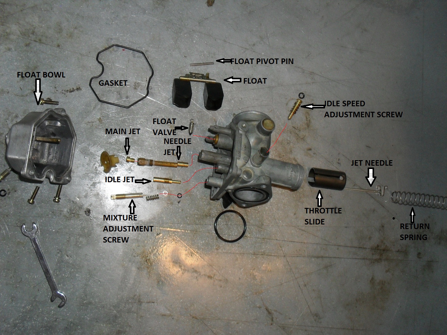
Here is a shot of all the major components laid out on the bench more or less in order. Always keep the parts from each individual carburetor together, never mix them up because there are some small differences in every set even if it just wear patterns. Some machines (but not this one) may even have different jetting between different cylinders so just play it safe and don’t mix your parts.

At this point instead of a big complicated looking rack of carbs, you are now just rebuilding 4 individual carbs with only a few differences from you average

dirt-bike carburetor.

This is one thing that is found on the early emission controlled Hondas (late 70s & early 80s) is this pilot mixture screw with the tab on it to prevent it from being rotated too far in on direction or another. The float bowl must be removed first to remove these screws. Of course if you doing this for an off road, race only machine 😉 you can carefully grind the tab off before re-assembly.

Another big difference on some machines is the presence of an air cut off valve often found under a cover like this. The purpose of this valve is to temporarily restrict the flow of air through idle air circuit when the throttle is suddenly snapped shut. This helps prevent that lean backfire that occurs on some motorcycles when you suddenly let off of the gas.

These valves were later eliminated from some models but the side cover is still there, but it’s just blank. Some folks will actually remove these and solder the holes closed, then re-jet the carbs extra rich to run without them but IMHO that is not the way to go. Yes I know that at 30 to 40 dollars & up each this is a damn expensive little part, but take my word for it if you replace them you will notice difference.

One nasty little surprise is the presence of pressed in pilot / slow / idle jets. pick your terminology but all three words refer to the little brass tube you see in the picture above. If you are restoring a completely stock bike with stock mufflers and airbox then I will recommend you do everything in your power to clean it without removing it. But if you cant get it clean or if you’re like me & think stock sucks don’t fret it can be changed. As far as I know there is only one source for the pressed in jets and that is Sirius Consolidated, one of my favorite purveyors of all things for motorcycle & powersport carburetors. Click here to check them out.

If you’re planning to change them out anyway grab them with a set of pliers, twist a little to break them free & pull them out.

I finally decided to break down and try ultrasonic cleaning. This is a cheapie from Harbor Freight. For my cleaning solution I am using 1 to 1 mixture of Simple Green & water. The only real drawback to this one is that you can only get 1 carburetor in it at the time, and even then the entire carb is not submerged. I just ran every one for the maximum cleaning cycle of 480 seconds and the flipped it over and ran it for the max cycle again. Be sure to put all of the parts for each carburetor in the cleaner, including all of the internal parts, along with the fuel & air vent tubes that run between the carbs.

Being the meticulous and detailed asshole that I am even after the ultrasonic cleaning I blow everything out good with an air gun and rinse well with aerosol carb cleaner. I also use Simple Green in my parts washer & have discovered that if you don’t rinse the parts afterwards they sometimes have soap residue on them. Plus I just like to be sure that all passages are clear.

Here’s a fresh clean carburetor ready to be re-assembled with all new jets. FYI with the K&N pod filters and the Mac Exhaust I am using #42 pilot jets and #120 main jets. and put my initial pilot mixture screw setting at 2 turns out. This set up turned out to work very well with only minor adjustments after starting the engine. I actually arrived at these numbers for my initial set up after perusing hundreds of posts at the HondaCB650.com & the SOHC4.net forums taking notes and basically picking out the jet sizes most commonly reported to be working successfully in these carbs on this bike with pod filters & aftermarket exhaust. Internet research is such a great time saver but remember to put your ego aside & your bullshit detector on high. You’ll have to wade through a river of fiction to get a few drops worth of facts.

Even armed with these numbers I was prepared to pull the whole thing back apart several times to get it right, but I got lucky this time. That does not mean these jet sizes and settings will work for you & your CB650, but they are as good a starting point as any. Back in the pre-internet days I was re-jetting a moderately modified DOHC CB750F and wound up pulling the carbs off and putting them back on a dozen times before I found the perfect combination of performance and street-ability. If you are modifying your motorcycle you should be prepared to do the same.

This was not a cheap process either, I replaced every single piece of rubber & all of the jets in this set of carbs. The cost just for parts set me back over $300 bucks plus shipping. The jets, air cut off valves & the accelerator pump, all came from Sirius Consolidated, everything else is genuine Honda OEM parts, even the o-rings on the crossover pipes.

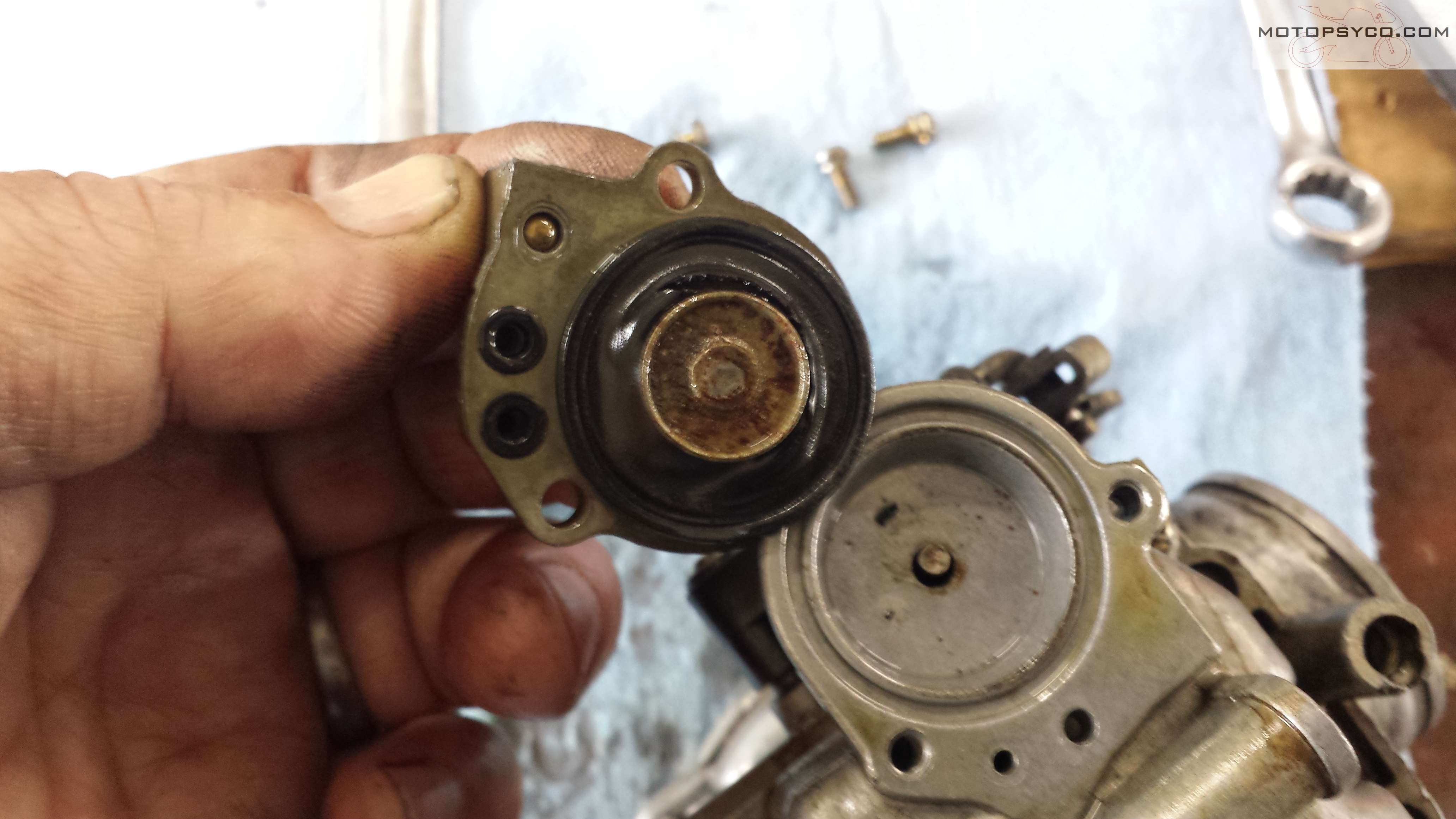
This is how the air cut off valve diaphragm, spring & o-ring fit into the body.

I preach a lot about service manuals, and yes I usually try to practice what I preach. This allowed me to verify that the float height really was supposed to be 12.6 mm like most of the fine folks on the net were saying. Trust but verify!

Lets talk about that accelerator pump thingy a little bit. It is usually mounted on the #2 carb like this one. It’s purpose is to squirt a little extra fuel into the engine if you suddenly yank the throttle open. Even though it only enriches one cylinder it helps to reduce the lean stumble that results from a sudden inrush of air when you twist the throttle as fast as you can. It’s also great to squirt a little extra fuel into the intake before starting a cold engine if needed.

It  lives under this little cover on the bottom of this carburetor.

Here it is laid out on the bench so you can see how it comes apart.

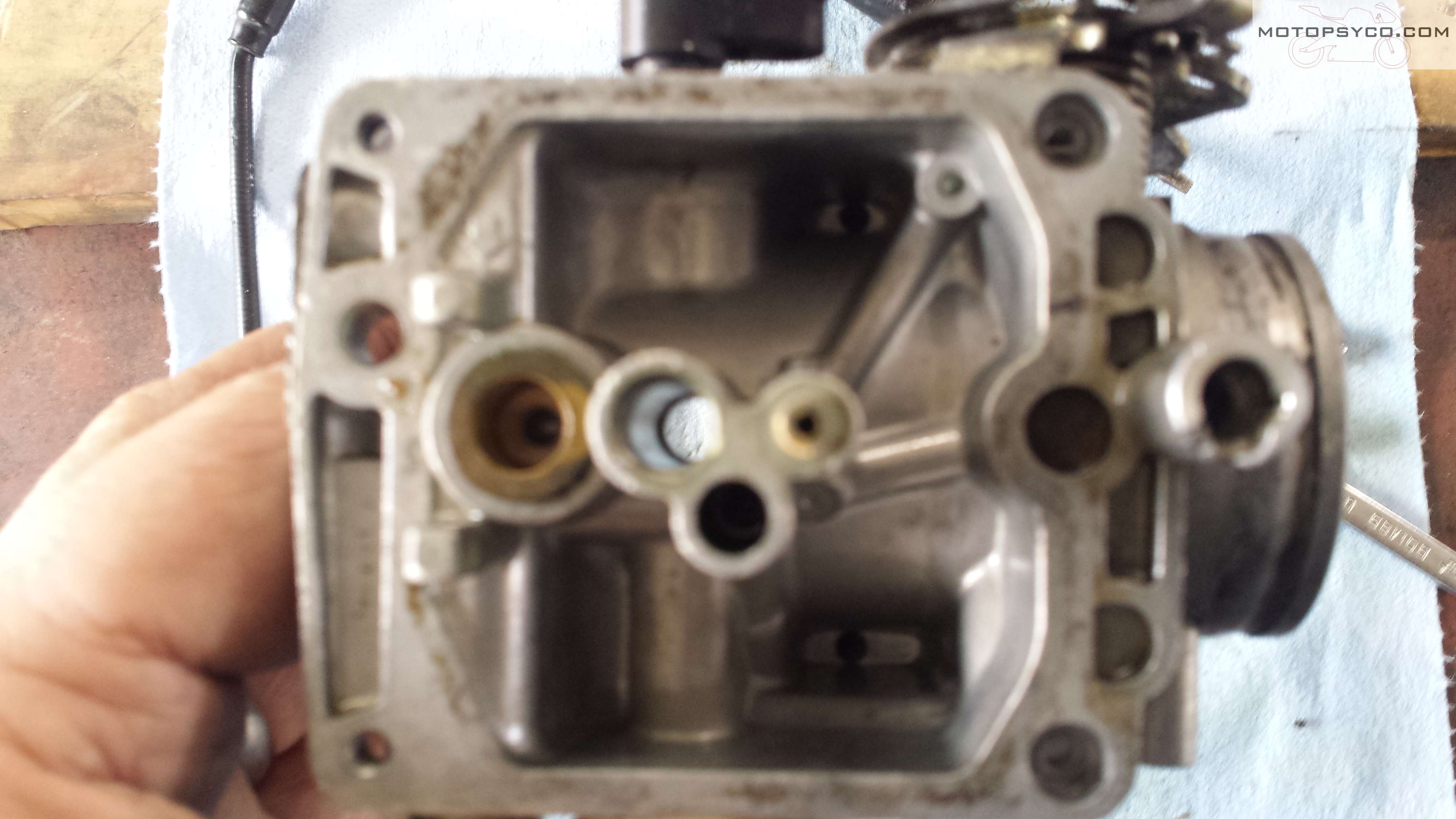
This shot is just to show you the differences in the #2 float bowl & the rest. These differences are there for the accelerator pump circuit.

At the time of this writing I have found no source for exact replacement parts for the CB650 accelerator pumps. I think this one is for a CL/CB450. The diaphragm is the same but the shaft is longer. so it will have to be cut to match the stock length.

I marked it and then clamped it into a vise with rubber jaws & then filed it to the correct length. Just remember if you get over excited & cut too much off that you have just screwed yourself out of the price of 18 bottles of Guinness Extra Stout.

Modifications are always a pain in the rear. These air filters don’t clear the choke linkage so even more modifications are required. It’s a vicious cycle I tell ya, and not for the faint of heart or the flat of wallet. Modifications beget more modifications & before you know it you have a complete custom motorcycle that will hopefully run at least as well as a stocker. ;0

Just a few more tips for you, re-assembly is pretty much the reverse of dis-assembly. Make sure you wind the throttle return spring up enough to close the slides when released, and always use some form of top quality name brand thread locker on these little screws holding the butterflies in place. If these come loose they can turn your fine running engine into junk if they get into the cylinder.

This picture shows how the spring connects the left & right choke shafts together. Once you have it all back together you should try to “bench Sync” the carbs. Basically you want to get it adjusted so that it appears the all of the slides are lifting at the same time & closing the same distance. A picture of the synchronization adjuster is shown somewhere further down in this post.

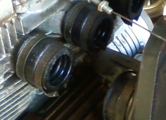
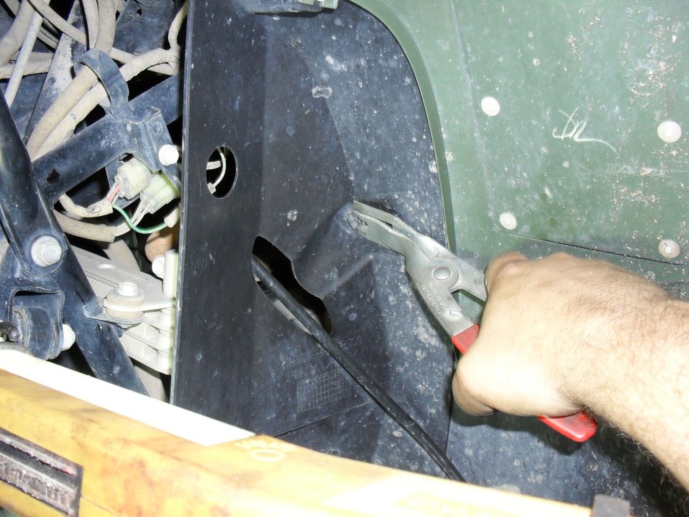
Now make sure all of the clamps are on the intake boots loosely, hook up your cables, & then lube the carb spigots & the inside of the rubber boots on the head.

Now push, pull, cuss, twist, shove & pray. If you are reusing the old boots they may be hardened and make this process a little harder. sometimes heating the rubber with a heat gun helps. Just remember that if they are damaged in any way and do not seal properly you must replace them.

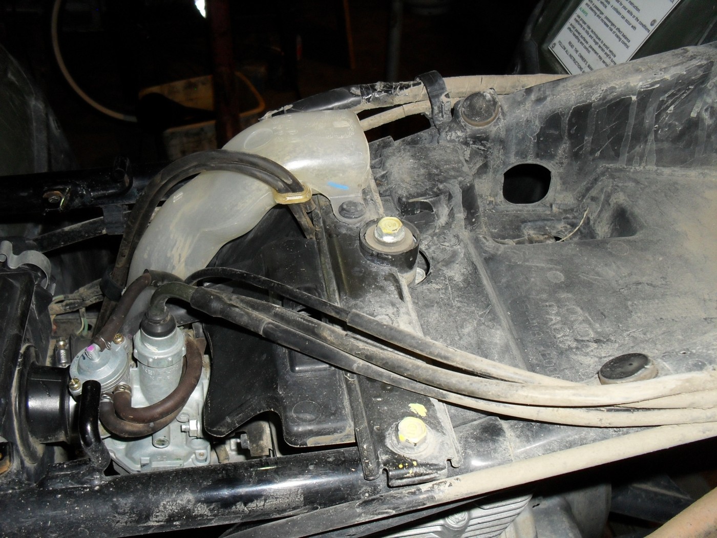
Here I am clamping everything down getting ready for the initial start up. I actually started the engine and let it warm up a bit before moving on the vacuum synchronization process.

Once I was satisfied that the engine was basically running okay & that there were no fuel or air leaks I shut off the engine & temporarily installed these adapters in place of the plugs on the engine side of each carburetor. Then each adapter gets a hose between it and this set of gauges.

Before you get started with this procedure it is usually a good idea to have a fan pointed at your engine & running. Sometimes this can take awhile & you don’t want to risk engine damage.

This picture shows the location of the adjuster screw in each carb. Make sure that you always tighten the lock nut securely when you are done adjusting the carbs. The number two carburetor does not have this adjustment on it, it is the baseline and you want to match the other 3 carbs to it. When you get it done all of the needles on all four vacuum gauges should rise & fall at the same time and to the same readings. Now you can put all the tops back on the carbs & begin road testing. Most run just fine, perhaps with a little tweaking of the pilot mixture screws and idle speed if needed. Just make sure that everything else, especially the ignition system is working properly too before road testing the carbs.

Ride as safe as you can & still have fun!

Peace Y’all

Random Tech Tip, Vintage Carburetor Intake Boots & Clamps

Today’s post is about those annoying rubber boots that attach your carburetors to the spigots on the head(s).

dry brittle old carb boots

dry brittle old carb boots

Often on old project bikes these are hardened and brittle, most of the time you can get the carbs out but it is almost impossible to get them back in. One thing that greatly helps is to take a heat gun and heat them up to soften them. Some people on the net have removed them and placed them in very hot water. Regardless of the method a small amount heat will help get them soft enough to reinstall the carbs. Just do not use an open flame or you will end up with a charred & useless mess. On some motorcycles these bolt to the head and on others they clamp to spigots cast into the head. If you are dealing with removal of old intake boots from a set of spigots like shown in the picture above prepare to be very patient. Don’t just grab a big screwdriver & start prying! First loosen & completely remove all of the clamps, then twist and pull them by hand until they will at least wiggle & turn on the spigots. If they still won’t come off you have to decide if it is worth the risk to pry them off. Choose your leverage points very carefully, if you have any doubt at all about being able to remove them safely or if you are working on a rare or valuable antique or classic machine this is where you break out a good sharp utility knife & cut them off. The cooling fins and other castings on most motorcycles are very thin and will often break before an old piece of dry rotted rubber will,so better to be safe than sorry.

intake manifold clamps

intake manifold clamps

Also be sure to look at the clamps when removing the boots. They are not just straight rubber hoses, often one end is bigger than the other, and the clamps are 2 different sizes as on this Honda CB650. The intake manifolds only fit one way but they have directional arrows on them, the clamps are not marked so be sure you note which ones go where.

That’s all for tonight, until next time have a fantastic life!

Dirtbike Carb 101 Part 3 Lets Put It Back Together!

If you are just joining this class and would like to read lesson 1 it can be found here.

Here is an exploded view of the carburetor with all of the key parts labeled. Everything has been cleaned or replaced and is now ready to be re-assembled!

motorcycle carb exploded view
The red lines indicate which hole the various parts go in.

The first thing you want to do when you pull the carburetor body out of the parts washer is to take a compressed air gun or a can of spray carb cleaner and blow out all of the  holes and passages in carburetor body. In general if you spray cleaner into any port on the body it should come out somewhere else. This is to get all of the passages completely clear. Do wear some eye protection while you are doing this.

motorcycle dirtbike mixture screw, main jet & idle jet
mixture screw, main jet & idle jet

In this picture I have already re-installed the needle jet, main jet holder & jet, and the idle or slow jet as some like to call it. The mixture adjustment screw is leaning up against the carb so you can see how the spring, washer, and o-ring fit over it in that order. This screw goes into the large hole on the right side of this picture. To install it pick up the carb with one hand, and hold it upright, with your other hand take the assembled mixture screw components and place them up into the hole and turn the screw until it has engaged the threads and will stay in. Return it to the workbench and turn the screw all the way in until it just touches the bottom. Do not tighten it! Do you remember how many turns you have to back it out to reach it’s original position that it was in before you removed it? I told you to write it down in lesson 2. If not check your service manual for the initial starting position, and be prepared to tweak it a little til you get a smooth transition from idle to accelerating.

Now it is time to re-install the float. There is usually a small wire retainer over the float valve that slides over a matching tab between the floats. Holding it together place the float valve into the brass ringed hole shown on the left side of the picture above. Then you should be able to slide the retainer pin in from one side to hold it into place, like this.

Honda xr 100 carb floats installed
carburetor floats installed


Don’t forget to put the little plastic shroud back on in the same way it came off.

Normally I wish vile and unspeakable torture on people whom make the mistake of using any type of gasket sealers on any type of fuel system assembly, but there is always an exception to every rule. In this case the fit of the float bowl o-ring into its groove on the float bowl was just not good enough to hold it into place so I applied a very thin film of  a gasoline resistant, Permatex product. A small amount of Permatex 1 or similar product. Use just barely enough to hold the gasket in place. After all you don’t want it squeezing out and stopping up your nice clean carburetor do you?

dirt bike carb float bowl gasket
carburetor float bowl gasket

Of course if the gasket will stay in place by itself long enough to get the float bowl screwed back into place I never put any kind of adhesive on it. but sometimes life just doesn’t work that way.

Once you have the float bowl back on it’s time to reassemble the slide. If you are replacing the needle  aka the metering rod, be sure you put the tiny little e clip on it in the same groove that the original one was in on the old needle. Push the needle in through the hole in the center and instal the retainer as shown.

metering rod & slide
retainer clip and needle nose pliers


This picture shows the retainer installed in the slide, exact positioning is not important just be sure you don’t block the slot on the side that the throttle cable goes through.

motorcycle metering rod retainer installed
motorcycle jet needle (metering rod) retainer installed


Now go bolt the carburetor back to the engine (remove the plug from the intake first if you used one), hook up the air cleaner hoses, new gas filter etc. This is the time to be sure the air filter is clean also.

Now back to the slide it only fits into the carb one way so if it does not smoothly slide all the way to the bottom something is wrong. This shot shows how the slide has a notch for the idle speed adjustment screw.

Honda xr 100 carb slide and spring
xr100 carburetor slide and spring

Now reverse the steps from lesson one to reinstall the slide to the end of the throttle cable under the top of the carburetor and then slide it into place and tighten the cap down by hand. Guess what? It is time to re-connect the gas tank and fill it with fresh fuel. I consider installing a new fuel filter mandatory and so should you.

motorcycle fuel filter
motorcycle fuel filter on Honda XR


Once you have the engine up and running you may need to set the idle speed using the idle speed screw as indicated here.

dirtbike idle speed adjustment
XR100 idle speed adjustment screw

Let the engine warm up thoroughly for a few minutes before making any final adjustments to either the idle speed screw or the pilot mixture screw. If you need to adjust anything make changes in very small increments.

Now go have some fun!

Dirt Bike Carburetor 101 Part 1 (how to clean a single cylinder motorcycle or atv carb)

Hello everyone and welcome to this multi-part lesson on the basics of carburetor  cleaning for single cylinder motorcycles. The cadaver we will be resuscitating in this lab is an 02 Honda XR100.

“barn fresh” xr100

Believe it or not this bike would still run with the choke on even with the dead gas and clogged jets, gotta love a Honda! This will be a general step by step guide to repairing carbs, so I will not be giving you the actual specifications as they vary so much from year to year on some bikes. As I’ve said before you need to obtain the specific information for your exact bike from a reputable source like say a service manual. For this first post let me show you how to remove the carburetor from this bike.

First let me say that it is possible to pull the carb from an XR100 without removing the bodywork, but A; you need to clean or replace the air filter and B; if it’s been sitting long enough to need the carburetor cleaned you need dispose of any fuel in the tank and clean it out before re-starting the bike after you finish the carb.

Now take off the side covers. This picture shows the location of the air filter cover on the XR100

Next look under the rear fender and remove the 2 nuts holding the seat on. Then pull it up and rearward to remove it.

I like to put the nuts and any spacers back on the studs like this so they will not get lost. In fact whenever possible I do this for all nuts and bolts as it keeps them from disappearing.

Now go the the fuel switch, valve or petcock, whichever terminology you use for it and turn off the flow of gas to the carburetor and disconnect the fuel line. Be prepared to cut it off with a knife and replace it if necessary.

Remove the rubber strap that holds down on the rear of the fuel tank and the two bolts at the front of the tank.

It is not required that you remove the shrouds like I did for this photo, I simply removed them so that I could show you the location of the bolts at the front of the gas tank.

After setting the gas tank aside in a safe location it is time to disconnect the throttle cable. On some models it attaches to an arm on the side of the carb but on simpler ones like this it is attached directly to the carb slide. Unscrew the cap as indicated by the screwdriver and pull the slide out.

This next shot is a little fuzzy but it indicates how the throttle cable is retained in the slide, and the following picture shows the slot in the side of the slide that allows you to remove it from the cable.

Now all you have to do is to compress the spring and push the end of the cable out of its hole, past the end of the slide, pull it out through the slot and then through the big hole at the top.

Here’s the removed and disassembled slide, jet needle, and return spring laid out for you to see.

Loosen the clamp holding the rubber hose from the air box to the carb and then remove the bolts attaching it to the engine and pull it out.

Yes I’m using the obstruction wrenches again. Two tools that I feel are must haves for any serious cycle mechanic are obstruction wrenches of decent quality and some extra long screwdrivers of the finest quality money can buy (i.e. Snap On etc.) Inexpensive wrenches are often okay but cheap screwdrivers will drive you bleeping crazy, by stripping out the soft metal heads on Japanese motorcycle screws.

Here’s a shot of the carburetor on the workbench. I like to use the red toolbox tray shown to help me organize the parts as I disassemble the carb, and to keep the parts from disappearing into the wormhole that exists behind my workbench. No part that falls back there is ever seen again, so I try to keep them from rolling of of the back edge. No dear reader I am not going to move the bench to look for them either. In my shop I coexist peacefully with all matter of snakes and spiders both harmless and venomous, and that is their territory and I stay out of it.

Don’t’ forget to protect the engine by plugging the intake hole while the carburetor is off.

I’ll show you the rest later, don’t forget to bookmark this page or to sign up for the email notification of updates on the right side of this page. Click here for part two!

Peace Y’all

Honda Recon 250 pg.2

The next order of business is to dis-connect the negative cable from the battery as shown here.

Remember any time you are working with any vehicle with a negative ground system (which is practically everything) always dis-connect the negative battery cable first and re-connect it last when you are working on the electrics.
The next 2 pics will show how I use the door panel tool to remove the plastic retainers from the bodywork. First you wedge up the sliding pin in the center enough to get the forks of the tool started under it.

Afterwards you can slide the tool into place as shown and pull the clip right out.
Of course you can just use a couple of screwdrivers or a pair of wire cutters to remove the clips. Don’t forget to look for clips or screws in hidden places like this.

To get the fuel tank out you first need to remove the handle for the fuel switch.

Once you have the tank out be sure to note the position of the various vent hoses and take note of the routing. If you pinch them closed during re-assembly your four wheeler may not run correctly, or may stall going up hill.

Once all the plastic is off it’s time to get down to the nitty-gritty. Now remove the foot pegs. This will save you lots of needless foul language and bleeding. Plus on some models you can’t get the engine out with them in the way.

Remove the foot brake and shifter after you get the pegs off and then drain the oil so it won’t be sloshing out all over the place when you lift the engine. It’ll take some weight off too.

Do take a little time now to put some penetrating oil on all of the exhaust system nuts and bolt that you can reach and let them soak a few minutes.

Then remove the plastic covers from the sides of the engine and the muffler & header as well. While I was doing this the head of one of the screws stripped out so I got out my extractor set to remove it. Normally I am a fan of inexpensive tools especially for the hobbyist but there are 2 things that I recommend that you buy the absolute best in the world even if you have to save up for it. The first is a good set of screw extractors and the other is a Phillips screwdriver set.

85% of the time I don’t even have to use the extractor because the left handed drill bit will walk the broken screw right out.
Back to our engine now it’s time to remove the carburetor and then unhook all of the other cables going into the engine. Leave the throttle and choke cables attached to the carburetor unless you plan to remove it to work on it also,

Be sure to loosen the clamps over the drive shaft boot!
The last item to get to is the reverse lock out cable located at the bottom rear of the engine under this little metal cover.

Now unbolt the 2 motor mounts on either side, carefully remove the spacers and slide the engine forward and tilt it as need to make the frame look like this.

Finally here’s a shot of the engine sitting on the workbench waiting to be completely disassembled… starting tomorrow.
Peace Y’all