The GTC Torque Converter for Minibikes & Go Karts Installation and Review

Here’s what came in the box. I ordered it from GoKarts USA mainly because it was listed as being a direct bolt on fit to directly replace the cheesy jackshaft plate & tensioner that this minibike came with. Despite what is said on some of the forums around the internet, this is a good quality unit that is made right here in the good old U.S.A. Yeah sure it’s got a couple of imported components in it, but suck it up sunshine that’s just the way the world is, we’re all on one rapidly shrinking planet and the market place is making it smaller everyday despite the best attempts by idiot politicians and knuckle dragging nationalists to stop it. Still it’s nice to see something made here that is of good quality and is price competitive. The backing plate is especially well machined & finished to the point that it is almost a shame to cover it up with a belt guard.

<contents of the GTC kit box>

Now this is not going to be a full complete step by step set of installation instructions, just an overview with a few tips. If have lost your kit instructions or have purchased a second hand unit without instructions please click here to get a set from the GTC website.  As always you may click on any picture here for a larger view.

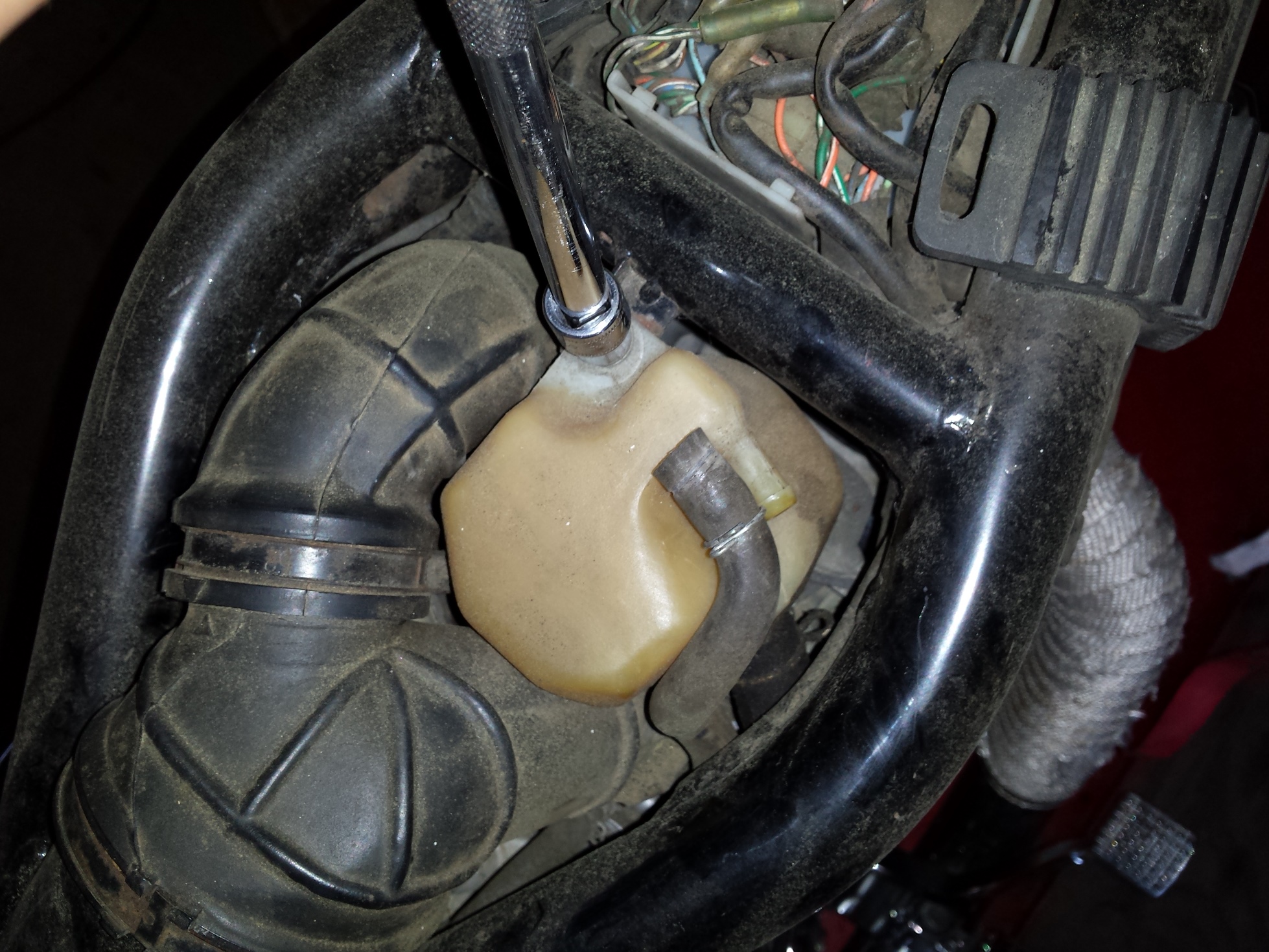
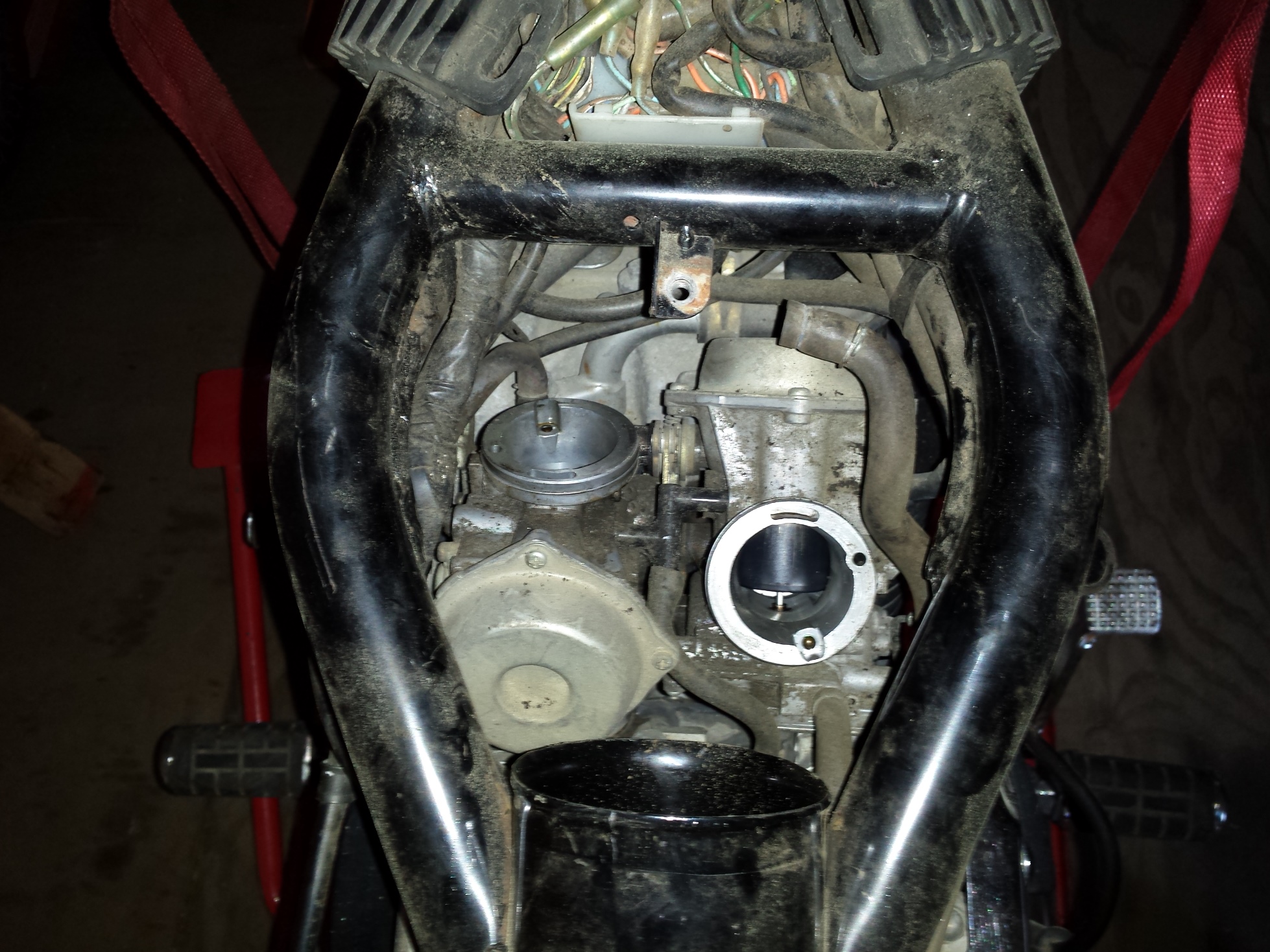
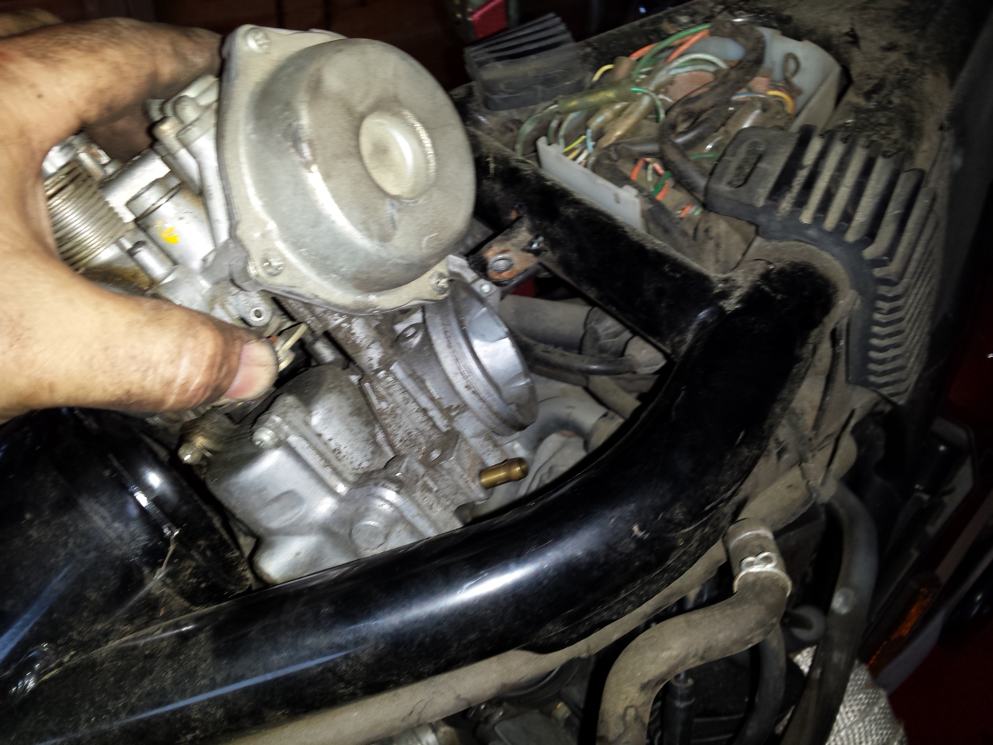
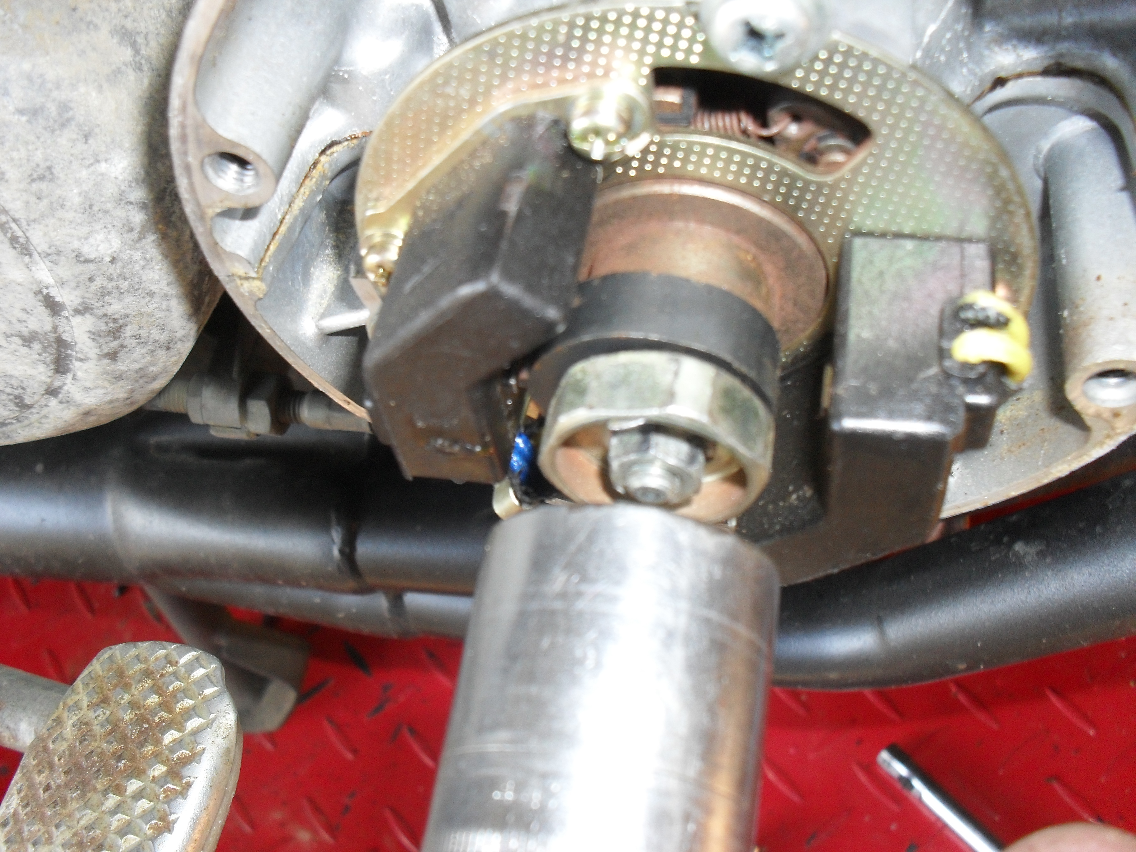
First you have to remove the original plate with the factory clutch & intermediate sprocket.

<Baja MB165 jackshaft chain tensioner>

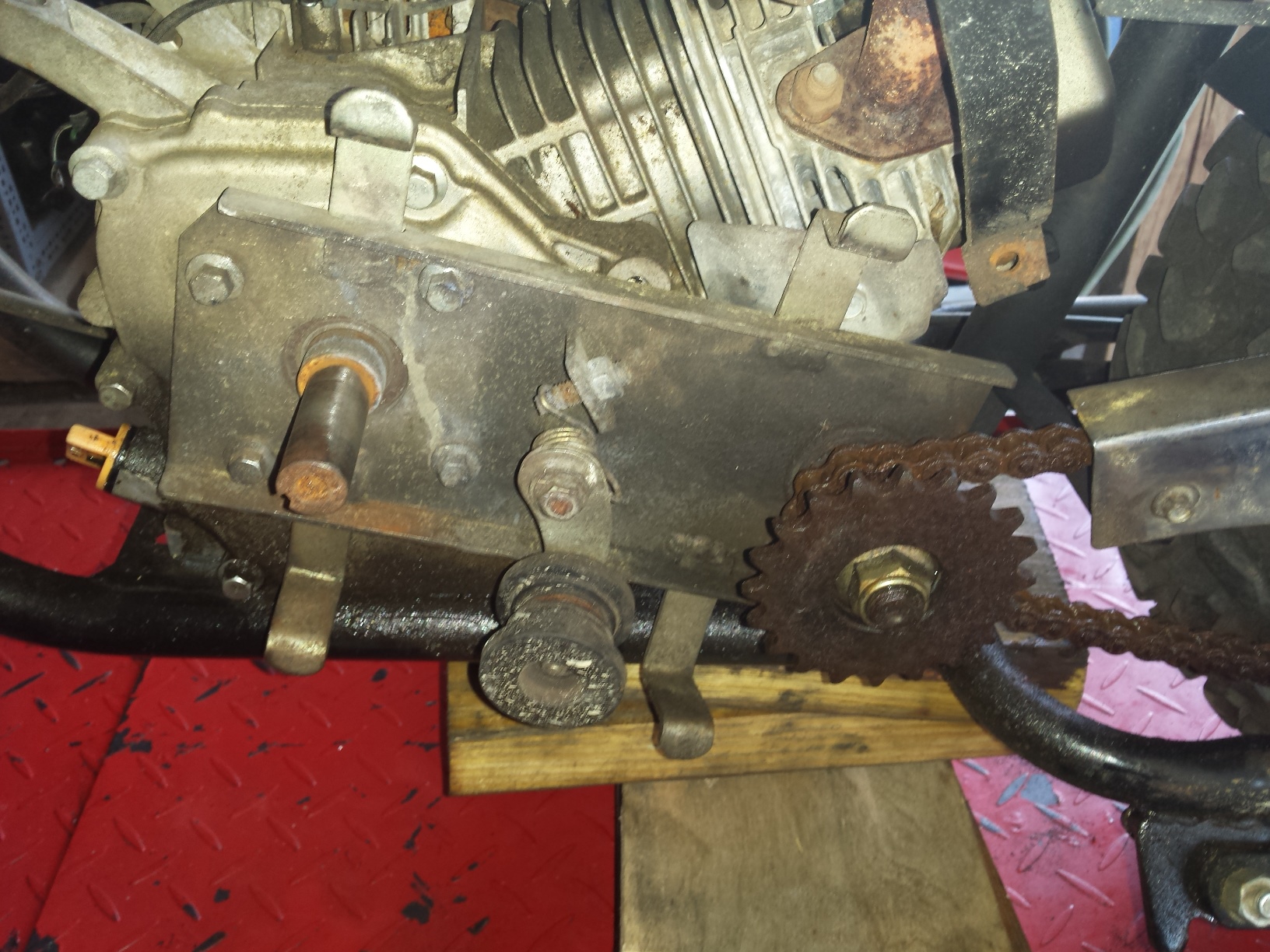
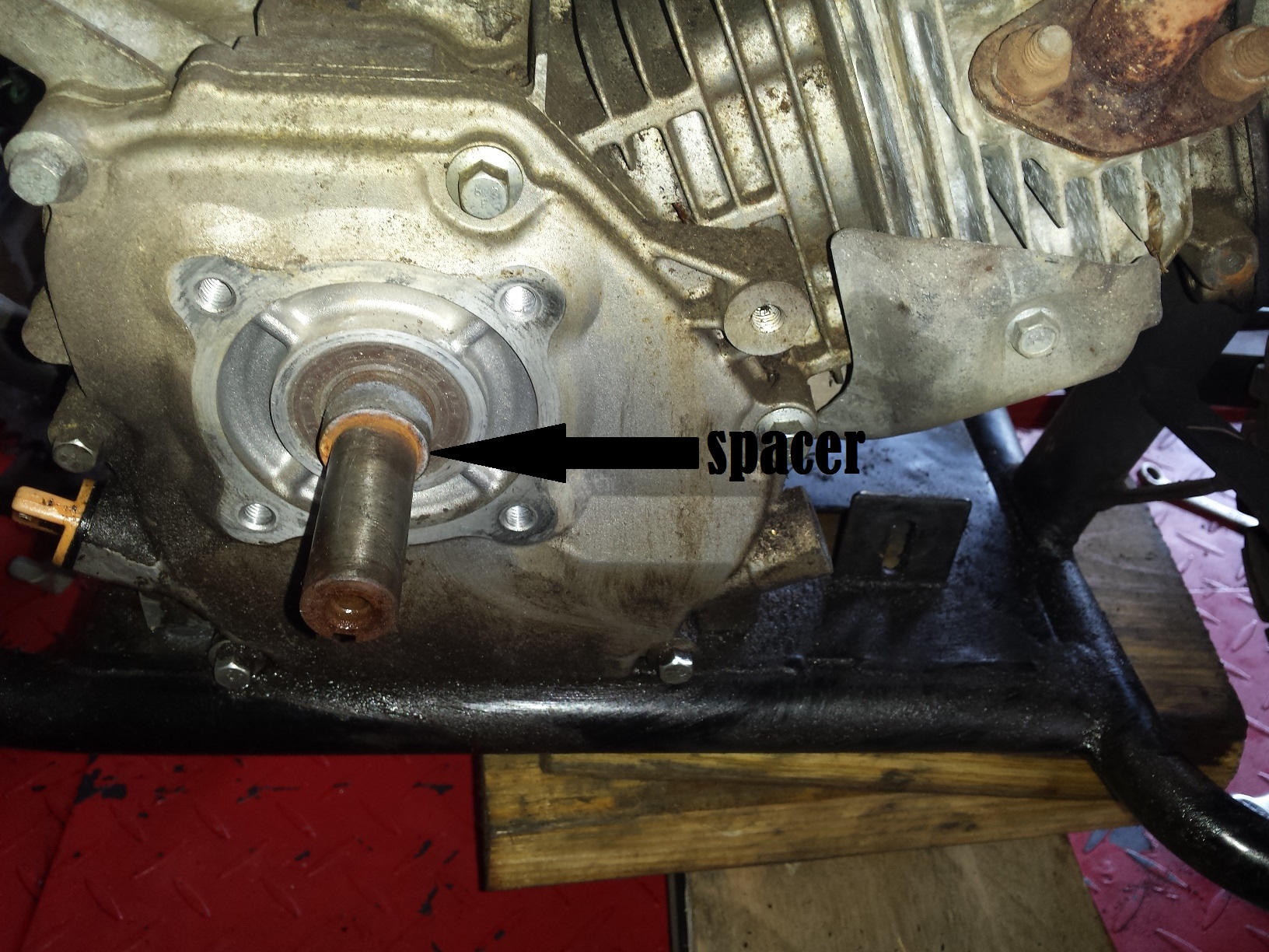
Make sure you remove all of the spacers from the end of the crankshaft, if you are doing this to an older engine oxidation may cause the spacer to look like an integral part of the crankshaft. If you don’t remove it the drive pulley won’t line up and you’ll be scratching your head for a few minutes like I was.

<baja minibike crankshaft spacer>

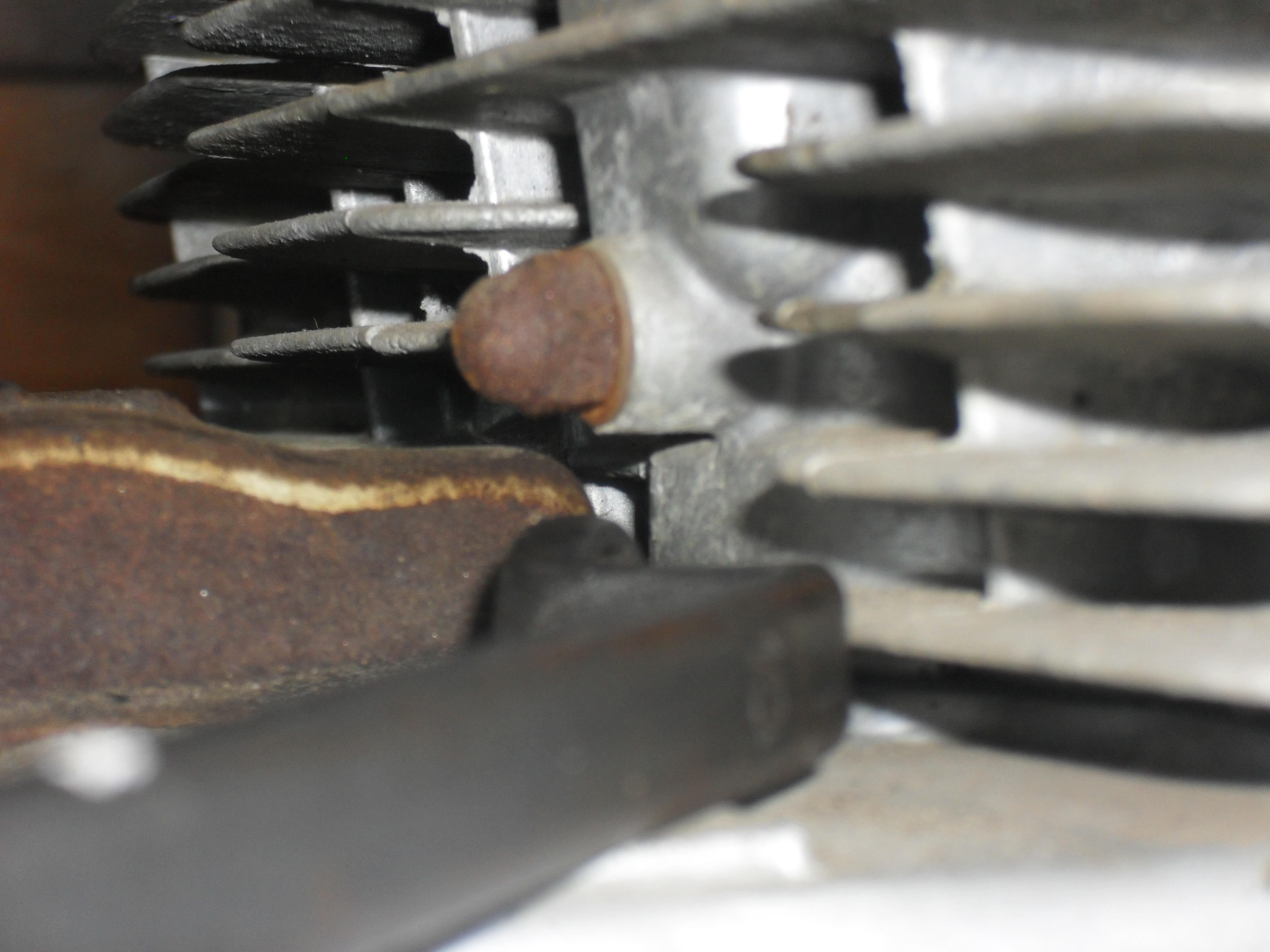
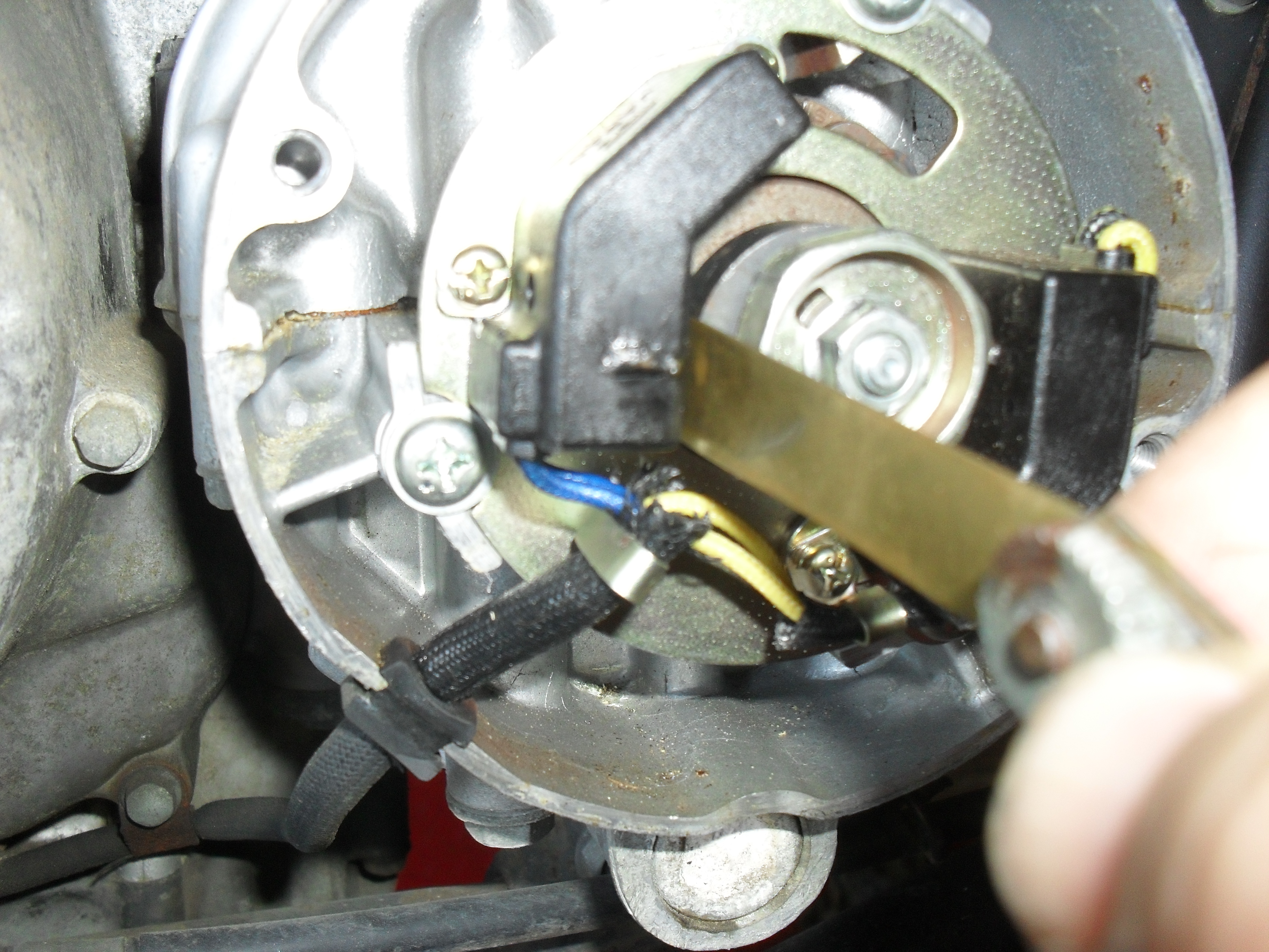
This tab is no longer used and will have to be flattened or removed for the torque converter to fit.

<remove this tab>

The kit comes with longer bolts to mount the plate if needed.

<GTC kit bolt>

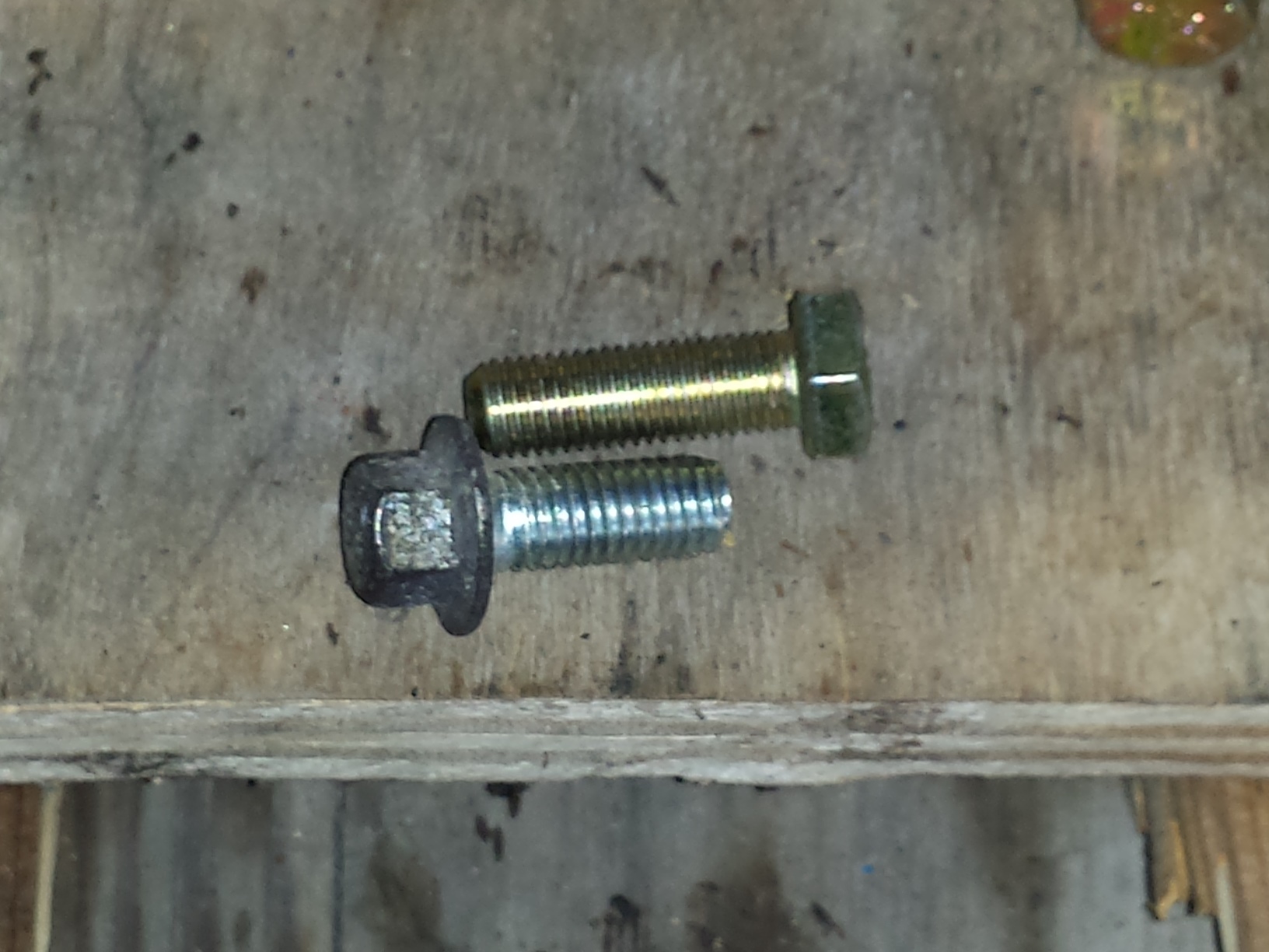
This particular installation just reused the stock bolts

<GTC mounting plate on Baja minibike>

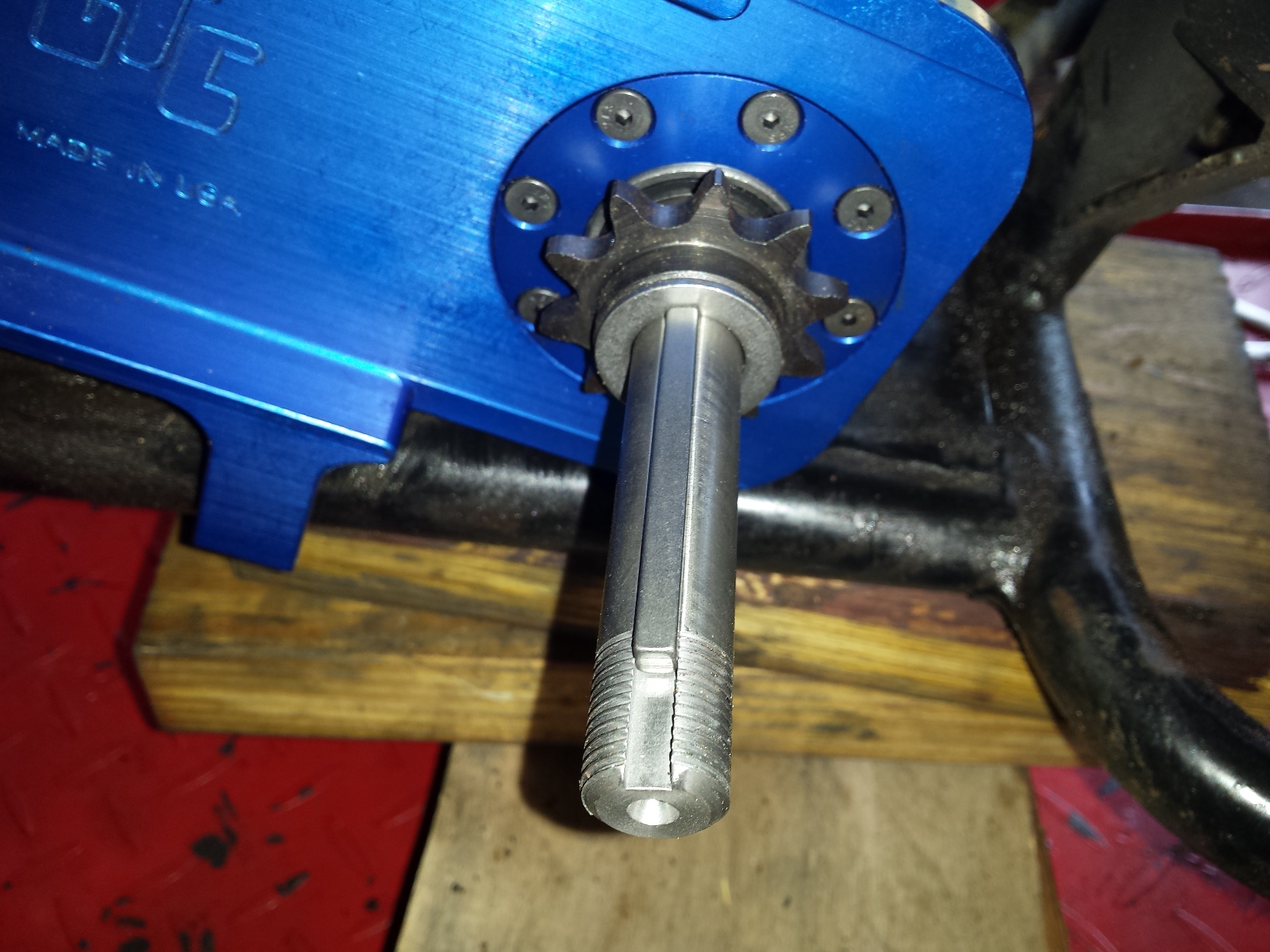
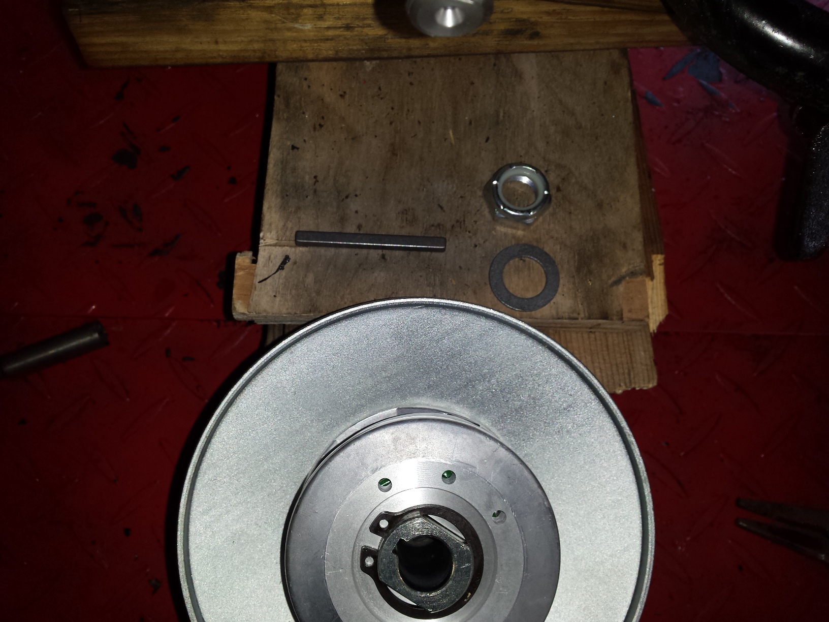
A picture of the driven shaft with the snap ring and washer installed.

<driven pulley shaft GTC torque converter>

Here it has been started through back of the mounting plate.

<installing the driven shaft>

Next get the chain sprocket, key & spacer,

<sprocket,spacer,key>

sprocket,spacer, & key

and slide them onto the driven shaft as shown here.

<This is what drives the rear wheel>

The next shot shows the driven pulley with it’s associated hardware, slide it all into place and install the nut finger tight at this time.

<GTC driven pulley>

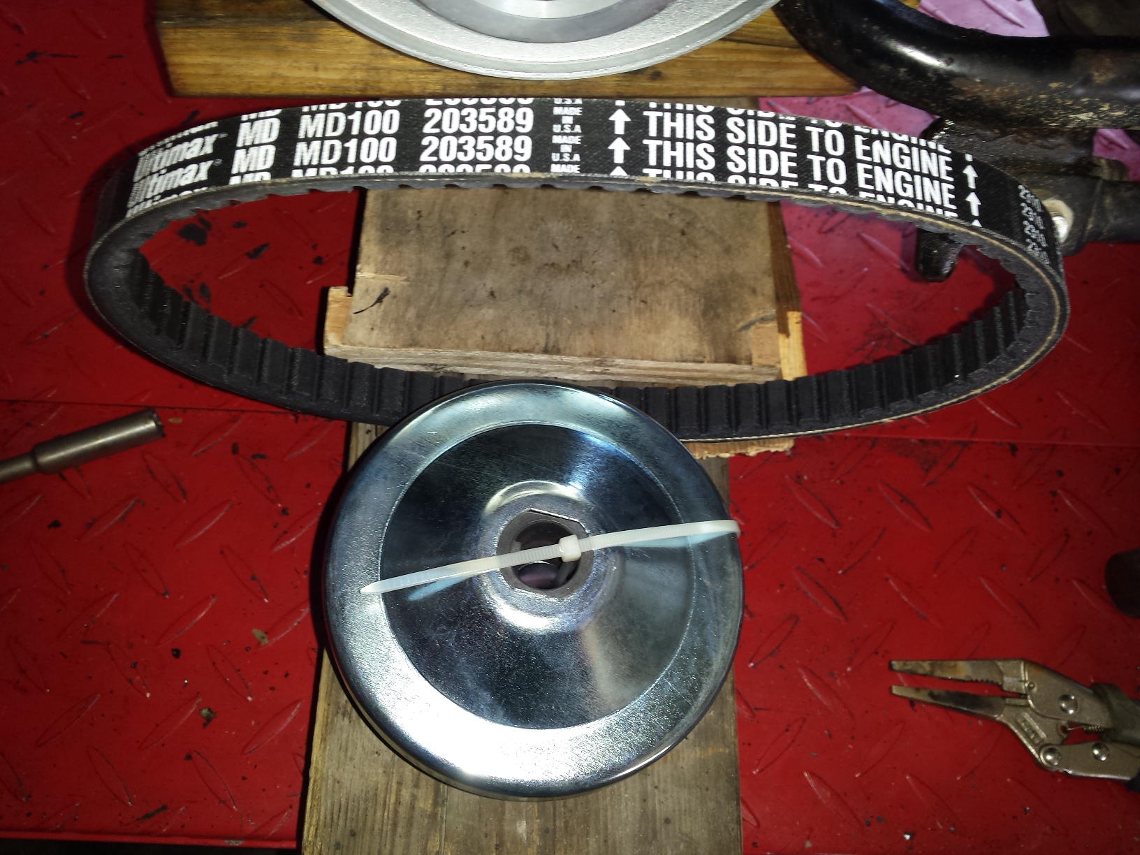
Here is the driving pulley & the belt. When you cut the tie wrap to install it take not of how the various parts & pieces fit together so you can re-install them correctly.

<torque converter drive pulley & belt>

I should have cleaned up the screw threads in this hole before I got this far, be sure to learn from my mistakes. BTW your engine must have an existing tapped hole in he end of the crankshaft or you cannot install a torque convertor. Be sure to check this before you spend your money as a few of the Honda clone engines are missing this feature.

<baja minibike tapped crankshaft>

The other drive pulley parts

<gtc drive pulley parts>

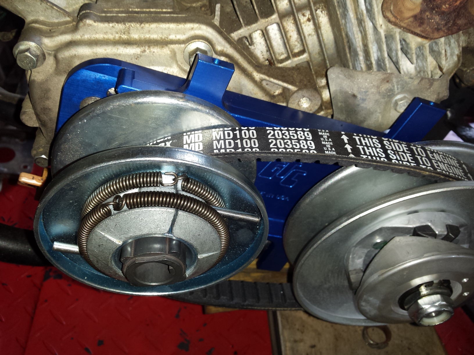
Stick the belt into place & begin assembling the drive pulley onto the end of the crankshaft.


<drive pulley parts on crankshaft>

Now that you’ve gotten everything assembled it is time to tighten it all down.

<GTC torque converter Baja minibike>

You really need to use a torque wrench and tighten the bolts & nuts to the torque specified in the instructions. Even a cheap one is more than good enough for everything the average home mechanic will ever do. If you over tighten the nut on the driven shaft it will pop the snap ring loose from the other side. Sure GTC could redesign the shaft to eliminate the snap ring but are you prepared to pay an additional 20 or 30 dollars for the kit to cover the cost of the additional machining and wasted material? Just use a torque wrench and you won’t have to worry about it.

<use a torque wrench dammit>

I did this install several months ago and have been driving this thing around the farm at least two or three times a week. While it did not transform my otherwise nearly stock MB165 into a 50 mph speed demon it did bump the top speed up enough to be much faster than a stock Baja minibike. Perhaps on a smooth surface with the governor removed it would but it is already able to outrun it’s own steering and stability out here in the deep soft sand & mud where I live.

<Baja heat warrior torque converter>

Four months ago when I installed this it was purely out of curiosity to see if it would really be an improvement, and it really is. The initial low speed engagement is much smoother than with a factory clutch allowing it to be driven at a lower speed than was possible with the clutch, while still increasing the top speed. The belt has proven durable and still looks fine after four months of hauling my big 200+ pound ass around the farm, down the dirt road, through the woods.  And when it does eventually wear out the belt is a little over half the price of a factory clutch. So is this worth spending the extra $200 buck on? If you are serious about actually riding your minibike, the answer is yes especially since the GTC TC2 is a direct bolt on that does not require engine mounting spacers to fit a stock Baja frame. Granted at this price it should come with the plastic belt guard but that really is my only complaint. At this time I’m running mine without the guard for a cool but possibly dangerous open primary look, but I don’t let kids ride it either.

Here’s a little video of the completed minibike so you can see how it works.

Peace Y’all


If you really enjoyed The GTC Torque Converter for Minibikes & Go Karts Installation and Review please visit our sponsor by clicking an ad below.

’97 Honda Shadow 1100 Carb Cleaning & Jetting ~ Part 2

In the last installment, I had removed this set of carburetors from a 97 Honda Shadow 1100, after washing all of the loose crud from the exterior it was time to begin dis-assembly. This is not going to be a full on complete step by step tutorial, but we will cover all of the highlights that are specific to this job. Here you can see that the float bowl is off and although the interior of this carb does not look that bad there is a thin film of of fuel varnish on all the surfaces so I definitely going to clean that out.

Don’t forget, that if you need to you can enlarge any picture on this blog by clicking on it.

<001 dynojet honda shadow kit>

As always when working with multiple carburetors, it is best to dis-assemble one at the time and to lay the parts out in a reasonably orderly fashion so that you can reinstall the parts back into the carb body that you removed them from. Below you can see the float bowl, float, jets, etc. are lying on the table and I’ve removed the top and am about to pull out the spring and slide.

<002 97 shadow 1100 slide spring>

Since my ultrasonic cleaner is small to prevent part mix ups I only put one carbs parts at the time in it. One nice thing about dealing with the Shadow carburetors is that both of the air cut off diaphragms are on the outside of both carb bodies and can be reached without breaking the carbs apart, this makes it much easier to clean those critical passages.

<003 carb parts ultrasonic cleaner>

Now it’s time to begin the modifications that will really wake your old Honda up and make it sing a new song of power and glory! You should wash the slides off good and inspect the diaphragms for holes, or rips, if you find any problems you will need to replace the diaphragm before proceeding but if all is well, look insde at the retainer and using either a proper JIS screwdriver or an 8mm socket twist the retainer counter clockwise about 1/4 of a turn until it pops loose and will fall out, remove the needle (aka the metering rod) being sure to note if there damage to the retainer or it’s spring.

<004 shadow ace jet needle retainer>

The Dynojet Research needles are packaged as shown, refer to the instructions in your jet kit for assembly instructions to match your particular application.

<005 dynojet research metering rod>

Here’s a quick shot of the slide, retainer & jet needle.

<006 metering rod removed honda 1100>

The next picture down is a comparison of the shape of the stock needle to a Dynojet needle. This difference in shape makes enough of a difference in flow that it should be used with the matching jets supplied in the kit. Likewise you can’t use your leftover kit jets in another bike without purchasing the correct needles.

The stock Honda needle is on top and the Dynojet needle is below it.

<007 needle jet comparison>

To simplify reinstalling the needle first insert it along with any spacers into the slide, then place the retainer into the end of an 8mm socket like this and then turn the slide upside down

<008 reinstall shadow ace jet needle>

while holding onto the needle as shown in the following picture andinsert the retainer into place and turning it to the locked position.

<009 metering rod install honda shadow>

Before I finish cleaning the bodies the idle mixture screws need to be removed. They are located under these caps on the sides of the carburetors. If you live in a state that requires visual emissions equipment inspection you should purchase new caps when you buy your carb kits or your bike will fail inspection if it does not have these caps on it.

<010 mixture screw cover>

Centerpunch the holes and the very carefully drill through the caps stopping as soon as the drill bit breaks through the caps so you do not damage your carbs.

<011 drill it out>

Then you a sheet metal screw of the right size (supplied in the Dynojet kit as is the drill bit) and screw it into the hole far enough to get a good grip on it & then

<012 screw it in>

yank it out with a pair of pliers. If you are just installing the jet kit without cleaning the carburetor turn the screws all the way in until seated and then back out 3 turns for your initial setting. If your are cleaning the carbs as I am here carefully remove the mixture screws, their springs, washers and o-rings and then thoroughly clean the carb bodies.

<013 pull it out>

In this shot below things are going back together now, just reverse the diss-assembly process checking all of your parts,float height, gaskets etc. and correcting any problems you find.

<014 honda ace carburetors>


<015 dynojet research jets>

When it is time to put in the main jet you have a decision to make based upon the modification level of your motorcycle. Since this particular bike had a pair of large tube drag pipes on it, I went ahead & put the largest jets in the kit in it. Don’t just automatically put the biggest jets in especially if you are running stock or quite aftermarket pipes and the factory air filter setup.

<016 97 honda shadow 1100 carbs>

You should also be prepared to do a bit of tweaking especially to the idle mixture screws to get a good idle with a good throttle response as you come off idle. One must also be prepared if necessary to pull the carburetors completely back out if need be to try a different set of jets or alter the jet needle cir-clip position for the best running. If you pay attention to the instructions in the kit this is not likely but it is a possibility.


<017 Carburetors ready to reinstall>

There you have it, if you’re contemplating doing this to your bike at home first make sure that it is running well, and that it has new plugs, and that the ignition and charging systems are up to spec, and that there are no other problems such as cracked intake boots that would cause you to have drivability issues. If you put a jet kit in a motorcycle that is not running right to start with, you are very likely to have a motorcycle with a jet kit in it that still does not run right.

Just take your time, read the directions, and keep everything as clean as possible and you should be able to make your old Shadow run & sound even better than it does now.

Peace Y’all

<97 Honda Shadow Ace>


97 Honda Shadow 1100 Carb Cleaning & Jetting ~ Part 1

<97 Honda Shadow American Classic Edition>

Let’s jump into another “how to” post! Above is today’s patient a 1997 Honda Shadow, a great riding 1100cc v-twin that while still running very well, needed a little tweaking.  These motorcycles came from the factory with the carburetors set up toward the lean end of the spectrum for emissions reasons. This led to some drivability issues on some of them, when you combine the original lean jetting with a set of drag pipes, and 17 years of ethanol contamination it was running mighty lean indeed. The engine had a tendency to run hot, hesitate on acceleration, and frequent backfiring on deceleration. So I am going to pull the carbs off, clean them up a bit and install a Dynojet Research jet kit in them. To hear what this bike sounds like before the carb tuning click here go to my youtube channel.

First get the bolt out of the rear of the passenger seat.

<001 ace seat bolt>

Then remove the 2 from beneath the drivers seat one on either side

<002 ace shadow seat bolt>

Lift it up and set it out of the way.

<003 honda shadow seat remove>

Locate the petcock and shut off the fuel.

<004 honda 1100 petcock off>

Remove the bolt at the rear of the tank,

<005 shadow 1100 tank bolt>

and the other one at the front of the tank.

<006 shadow ace tank bolt>

Disconnect the fuel line from the petcock.

<007 remove fuel hose>

afterwards lift the tank high enough to remove this vent hose from the bottom

<008 honda shadow tank vent>

After you have removed the gas tank and placed it in a safe location this is what you should see.

<009 honda 1100 air inlet>

The yellow plastic container is there to catch any oil that happens to emanate from the crankcase ventilation system, so unbolt it,

<010 shadow ace oil breather catch>

pull the hoses loose, and set it out of the way.

<011 crankcase vent hose honda>

Next loosen the hose clamps on the rubber piping that leads from the frame to the inlet of the carburetors.

<012 honda shadow air hose removal>

Now we can finally see the carbs!

<013 there be the carburetors>

Time to remove the throttle cables, remove the 2 screws (indicated by arrows) and you will be able to get the cables out of the pulley on the end of the butterfly shaft.

<014 1100 shadow throttle cable>

The cold start enrichener is next. These 2 little plungers take the place of choke flaps on the most of the last production carbureted motorcycles. Instead of blocking the air they just add more gas. It works well but is a bit more aggravating to remove. I used to have a special home made tool for getting these out but it has been at least 10 years since I saw it last so I just you whatever combination of open wrench & needle nose pliers that allows me to remove & reinstall them without boogering them up.

<015 honda enrichener aka choke>

Here I am holding one of the enrichment plungers so you can see what it looks like on the inside.

<016 cold start enrichner honda ace>

Go around to the right side of the bike and pull the hoses in this tee junction that was connected to the crankcase vent reservoir and fold them back out of the way.

<017 shadow crankcase vent hose>

The rear spark plug wire runs through a loom that is attached to the right carburetor so remove it and the enrichener  on this side.

<018 rear plug wire standoff 1100 shadow>

You can reach under the carbs now & loosen the clamps holding the carbs to the spigots.

<019 carb boot clamps honda shadow>

With a rocking and twisting motion you should be able to pop the carburetors loose, but dont rush to pull them up out of the frame just yet.

<020 pop the carburetors loose>

Before you try to pull them all the way out remove all of the fuel lines and vent hoses, being sure to note which hose goes to which barb.

<021 pull off all the hoses>

These carbs come out of the top, just tilt them up sideways and turn them as needed, this is actually much easier than most Japanese cruisers of the same time period that require you to remove the carbs from the side.

<022 shadow carbs come out the top.>

Here are the carbs sitting on the workbench ready for cleaning. The next step is into the parts washer to get all of the exterior crud off for dis-assembly.

<023 dirty nast filthy carburetors>

Keep checking back as I will be posting part 2 of this series very soon.

Peace Y’all

Part 2 of this how to article is up & you can reach it by clicking here.


How To Adjust Valve Lash (1980 Honda CB650 SOHC)

<Honda 650 SOHC Valve adjusters>

Here I’ve already removed the tank and all of the necessary engine covers.

Since I have already put enough miles on this bike since I got it running to warrant an oil change I decided to re-check the valve adjustment for two reasons; one is that as long as the engine had been sitting without running I want to keep a close eye on it for a while & two so that I could show everyone how I do it. As you can see in the photo above I’ve already removed the gas tank, all four spark plugs  and all of the appropriate engine covers. The first thing to do before you adjust the valve lash is to adjust the cam chain tensioner. On a 1980 Honda CB650 this is done by loosening the nut on the rear of the cylinder just a little bit. Do not remove it just loosen it some

Honda CB650 Cam Chain Tensioner Nut

This is the nut you loosen to adjust the cam chain tensioner.

Then put the correct size wrench on the hex spacer behind the nut at the ignition unit on the right side of the engine. Then rotate the wrench clockwise slowly 4 to 5 turns as you simultaneously tighten the lock nut that you loosened at the beginning of this step. This is also the first thing you should try if you own a motorcycle and you can hear the cam chain rattling, but if after making the correct adjustments you still have a rattle then it will be time to start replacing parts. Keep the wrench that you used to turn the crankshaft handy, you are gonna need it a few more times.

1980 Honda Ignition Pulse Generators

The Clymer manual describes this as a 15/16″ nut. That is wrong this is a 24mm. OOPS

Here in this picture taken on the left side of the engine you can see 2 of the three openings in which we will be working to check & set the valve lash. The adjusters for the intake valves are on the back of the head in front of the carburetors and the exhaust valve adjusters are on the front of the head behind where the exhaust pipes stick out. The first step is to get the number 1 cylinder to top dead center. Take your large wrench and rotate the crankshaft clockwise and watch for the intake rocker arm on the first cylinder to drop down into the head and start to rise back up. Then look at the timing marks on the ignition advance unit (photo is further down the page) and continue to slowly turn the engine until the 1.4 T mark is aligned with the pointer that is cast into the crankcase.

Honda SOHC Cam & Rockers

The camshaft & rocker arms are in the left hole & one of the adjusters is in the right hole.

At this point both the intake & exhaust valve on cylinder number one should be loose enough both rocker arms to be wiggled. If not you either have a valve that is way too tight or you did not stop turning the crankshaft at the right mark, either way you should verify which problem you have before moving on. a simple way to see if the cylinder is at top dead center is to take a long small diameter wooden or plastic dowel and insert it into the spark plug hole. If the piston is at the top of the cylinder the dowel will not go in very far at all.

With the number one piston at TDC on a 1980 CB650 you should be able to adjust both valves on the number one cylinder, The exhaust valve on number two, & the intake valve on number three. Once you have those done you need to repeat the step above but this time watch the intake rocker of cylinder 4 on the right side of the motor cycle. With that one at TDC you can adjust both valves on number four, the exhaust valve on number three, and the intake valve of number two.

Lets talk about tools for a little bit. All of the shop manuals show a special tool for adjusting the valves, but the simple truth of the matter is that for a number of engines you don’t need them and this CB650 is one such example. For the lock nut, I just clamped a pair of Vise Grips around an old cheap 10mm socket that I have on hand and then just used the proper size of flat-head screwdriver to turn the adjustment screw with. Works great for me on this motorcycle, your mileage may vary, if you break something I’m not responsible, etc.

tools for valve adjustment

Macgyver was an amateur!

Speaking of tools let’s get the feeler gauges to set the valves with. The ones that I use are from Snapon and are about a foot long. The also came with a nifty holder that is very handy for working with the really thinner sizes in hard to reach places. The intake valve lash setting for this generation of Honda CB650 is .05mm (.002 inches) and the exhaust setting is .076mm (.003). So to do this job I will get out three feeler gauges in sizes .002,.003 & .004 (.1mm). Why three sizes? I’ll explain in a minute.

The next picture is of the .002 feeler gauge slipped in between the rocker arm & camshaft. This is where you measure the lash on this engine. Basically what I do is turn the adjustment screw until I can just slip the feeler gauge into place with just a little bit of wiggling. You should tighten the lock nut each time you do this as it may affect the final adjustment. If you tighten the lock nut and find that your lash setting has changed tighten the adjustment screw a bit to compensate, re-tighten the lock nut and check it again. Usually after I do all of this, and I am satisfied with my setting, I then take the next larger feeler gauge (.003) and try to insert it into the gap. If it doesn’t fit great I move on to the next one but if it slips in I readjust the lash until the correct sizes slips in fairly easy but the next size up wont go in. You may wonder why not just set it a little tight and not worry about it? I like to set these things exactly as needed for the best performance. The other reason is the way that motorcycle engine valves wear. Very rarely is there any wear at the top of the valve, most of the wear occurs where the valve closes at the valve seat in the head, this causes the valve lash to get tighter as the engine wears & not looser. This is especially problematic when you are running old motorcycles on the toxic, corrosive, & environmentally unsound corn juice that passes for gasoline in this day & time. If you must err on the side of caution it would be a little tiny bit better for your valve lash to be just a hair too loose than to be to tight.

<setting the 1980 CB650C intake valve lash>

For really thin feeler gauges like this .002 I recommend a holder like this one from Snapon tools.

Next take the .003 feeler gauge & set the exhaust valves as shown here. Then use the .004 gauge to make sure your adjustment is just right. It is especially critical not to over tighten the exhaust valve lash. If the valve wears down and is not able to close all the way due to a lack of clearance you may get a burned valve & a big repair bill.

<adjusting the 1980 CB650 exhaust valve lash>

If you have a late 70s or early 80s Honda with the factory electronic ignition you definitely want to perform this next step. First get yourself a set of nonmagnetic feeler gauges. DO NOT not use steel feeler gauges to set the magnetic pickups aka pulse generators on these bikes.

Brass non-magnetic feeler gauges

Non-magnetic feeler gauges are a necessity to set air gap on the pulse generator of most OEM electronic ignitions of this time period.

The range of settings for the air gap between the pulse generators (black boxes in the picture below) and the trigger mounted on the end of the crankshaft is .012-.016 inches (0.3-0.4mm) You can also see the pointer & the timing marks that I mentioned above in this picture.

<80 CB650 timing marks, pulsers & advance plate>

1980 CB650 timing marks, pulse generators & advance plate

Believe it or not I have never seen any motorcycles with this gap set correctly from the factory, but the system is still good enough so that most bikes run without any problems whatsoever. Still if you have one of these and it runs okay except for a little surging & hesitation the pulse generator air gap should be the first thing you check. To set mine I just rotate the engine until the trigger ( little square nib sticking out of the crankshaft ) is aligned with nib on the pickup, loosen up the adjustment screws, stick the feeler gauge in place, & hold it all together while tightening the screws back down. Then rotate & repeat to do the other one.

<Honda electronic Pulse generator Air Gap>

This makes a huge difference in engine performance if it is set correctly.

There you have it, put a little lube on the advance mechanism behind the plate, reinstall all of your covers, spark plugs & fuel tank. Now it’s time to fire it up & check it out. Once you are sure that you did everything correctly & your engine is sounding just the way it should take it out for a ride & enjoy the fruits of your labor!

Peace Y’all

How to Deal With Stuck of Frozen Screws & Bolts

I was invited to be a Guest Blogger over at the Clark Heintz Tools blog, so I sat down and wrote for them what I hope is a nice informative article on one of the most vexing problems anyone can have when working on a motorcycle or bicycle. Click here to go check it out.

There is even a picture of the infamous old  Honda oil filter bolt showing just exactly what you might have to do to remove one…..

If you like the post let them know, if you don’t let me know.

Peace Y’all


A Custom Battery Tray & Other Stuff

Just thought I’d do a quick update on some of the things that I have done with my CB650 project. I have been working on it a little at the time between my normal day job, a few bikes & atv’s for other people, & some painting (airbrush practice & landscape oil painting). Since I’ve decided to go with the “rat suburban assault scrambler” look some of the things about this project have gotten easier, but other design ideas require just a little more ingenuity. Rather than sawing off the back half of the frame & welding in a new seat loop as required to get the proper cafe racer look I am opting for a modified stock seat with a 74 CB750 tank, but I still wanted to eliminate the stock side panels. My plan now is to replace the side covers with 2 pieces cut from some rusty old expanded metal sheet I have lying around. To do that I still needed to modify the mounts for the electrics, and since I will be using a Shorai lithium battery that is much smaller than stock, a custom battery tray was in order also. Since this is a rat I decided to do this with nothing but materials I already had on hand. After sitting down & staring at it a while with my note book, pencil & ruler in my hand I came up with a basic design that tucks everything up high, bolts into the stock mounts, & allows me to reuse the inner fender to protect the electronics. Here’s how it goes…

First I removed the stock battery tray, along with the airbox & some other now useless items. Then I drilled out all of the spot welds holding the mounts, & various brackets to it.

butchering a Honda CB650 battery box

butchering a Honda CB650 battery box

In the spirit of my deep back country roots I decided to make do with the stuff I had on hand & not buy any new stuff to make this from, so this left over shelf divider that was destined for the scrap bin will get to live on as a motorcycle part. Here it is with all of the brackets & mounts salvaged from the original battery box.

custom built motorcycle parts

a custom battery & electronics tray in kit form 😉

Then using my band saw I cut the tray to shape & bent it in a vise.

<custom motorcycle battery tray blank>

Then I bolted the stock mounts back into place using the original hardware & clamped the tray in between them. Since I do not have a tig box for my welder (YET) I simply use a 1/16″ 6013 rod to tack the pieces together without burning through the sheet metal too much.

tack welding battery box

tack welding battery box

After I got it tacked together with the stick welder I took it out and flipped it over & then brazed it securely together with the oxy-acetelyne torch. Then I laid out the various components such as the rectifier, turn signal flasher & etc & then brazed those mounts to the bottom of the plate.

custom rat motorcycle electronics mount

custom rat motorcycle electronics mount

I know it looks awful, but I might just leave it that way, this is a rat after all. I will have to sort & secure all the wiring though, because neatly sorted wiring is easier to trouble shoot in the future & is less likely to develop problems that need trouble shooting.

Here’s a view from the top side showing the Shorai battery lying on it’s side. I still need to make a plastic box to keep the battery from sliding around. Since my day job is doing design work using Solidworks, I may just draw one up & have it printed out using a 3d printer. If not I’ll form one out of ABS sheet.

<Honda CB650 battery box Shorai LFX>

fits just right!

I can’t say enough good things about these batteries, they’re light, powerful & durable. I’ve installed them in a couple of customer bikes, this one, and even have one in my lawn mower! Sure the cost a little more than the lead acid batteries, but are in my opinion a threefold improvement in all areas. I do sell these & would be happy to quote you one if you contact me.

Here a couple of other items that have been added, first an Ebay find of a 74 Honda CB750 fuel tank. This fit with modified rubbers & a custom rear mount. I’ll show you some more details later after I have it all worked out with the seat fitment. but I think it looks really good on here!

Honda CB650 with CB750 tank

Honda CB650 with CB750 tank

Another Ebay purchase is this 1970 Honda CL450 Scrambler. I bought the whole bike just to get the handlebars!

1970 Honda CL450

1970 Honda CL450

It’s pretty much seized up and there’s no paper work but the handlebars gave me exactly the look I wanted for my project. Good solid bars with just enough crust to blend in. No need to treat a new set of bars to a faux patina.

1970 CL450 handlebar on 80 CB650

1970 CL450 handlebar on 80 CB650

The CL450 will be parted, I plan to keep the frame, engine, carbs, gauges, charging system, fork & wheels. All of the sheetmetal and the exhaust are up for grabs to my fellow hobbyists who want them. The fuel tank is rusty bondoed junk but everything else is decent. Contact me using the form below.

I had a few other adventures including dealing with a stuck oil filter bolt that I’ll go over with you soon including how far I had to go to get it out.

Peace Y’all

2012 in review Thanks to all of my readers!

2012 was a very good year for motopsyco.com, I hope to entertain and inform you even more in the years ahead! Thhank you all, come back often and bring friends.

Peace Y’all


The WordPress.com stats helper monkeys prepared a 2012 annual report for this blog.

Here’s an excerpt:

600 people reached the top of Mt. Everest in 2012. This blog got about 12,000 views in 2012. If every person who reached the top of Mt. Everest viewed this blog, it would have taken 20 years to get that many views.

Click here to see the complete report.

Installing Dunstall Replica Mufflers on an EX250 Ninja

When I last posted about my work on the Minimum Ninja, you saw a photo of a damaged and worn out aftermarket exhaust header. When my wife bought this as an abandoned bike from the back lot of a Kawasaki dealer for a c-note a few years ago, it had the Yoshi pipe on it, so I had to  buy a stock head pipe. If your Ninja has the stock mufflers you don’t have to do all of this work, just figure out where to cut them off, put the right adapters in the new muffler, make some brackets and go. Not being that fortunate I had to do a little more work, not a problem for me tinkering on a motorcycle is as much fun as riding one. I started with a piece of 1 1/4″ water pipe,way bigger than the exhaust pipe but a good enough match to the size of the flange around the pipe to be easy to weld.

1 1/4 inch water pipe nipple

So I stuck it in my handy dandy pipe bender and bent it to the desired angle. Please note that pipe benders like this will NOT bend thin wall tubing without crushing it, they are meant to bend schedule 40 steel pipe or very thick walled DOM tubing.

An inexpensive pipe bender

After bending and cutting it to the right length grind one down enough to slip into the new muffler. And absolutely grind away all of the galvanizing from the area to be welded. The fumes given of by burning galvanizing are very dangerous. Use all necessary precautions. I would have used black pipe but the hardware store was closed and Lowes did not carry it in this size.

home made muffler adapter

one is done and one more to go

Then I mocked it all up on the bike and tack welded the adapters to the head pipes.

Ninja Dunstall muffler adapter mockup

Mocked up for tack weld

After that I pulled everything back off and seal welded the pipes together, cleaned off the scale and shot the pipes with a coat of high heat paint

tack welding completed

tack welding completed

pipes seal welded & painted

pipes seal welded & painted

Then I wrapped the entire head pipe with header wrap and reinstalled everything.

Head pipe wrapped with 2" wide fiberglass wrap

Head pipe wrapped with 2″ wide fiberglass wrap

I did take the centerstand off, 😦 it just did not work with the new pipes. Besides now I have a motorcycle lift table when I need to work on it now.

Next time I’ll show you how I lined the fuel tank with tank Kreem. An oil & plug change how to is in the works too.

Peace Y’all

 fiberglass header wrap

P.S. This thing sounds really good now and is not nearly as loud as it was.

Review of the Harbor Freight Motorcycle Lift Table

I’ve been wanting one of these for a long time. For years I used a wooden table or a chain hoist to lift motorcycles up for repairs when I just could not bear to get down on the floor to work on them. As I’ve gotten older the combination of a weaker back and a fatter wallet has made this purchase a lot easier to justify. So when the September issue of my favorite motorcycle magazine arrived on my Kindle with a coupon to purchase this lift for $299 I bought a print copy ASAP & clipped the coupon.

Ironically enough it took me 2 weeks to purchase this from either of the 2 nearby Harbor Freight stores. Unfortunately this led to my first real negative experience with a company that I have enjoyed doing business with for years. Last Saturday I went to my closest store in Florence S.C. and they were out of stock, so I called the store in Dillon an hour drive from here and they were also out, but told me they were expecting a shipment on Thursday. Yesterday, I was in Florence and they were still out, so I called the Dillon store and gave them the item number and was informed they had some in stock. So I gassed up my van and rolled up the interstate to that store, imagine my shock when I handed the clerk my coupon and was told that they were out of stock. When I mentioned that I had just called and had been informed that they were in stock. Then she went back to the computer and “found” one for me. Probably just a human error but if you are using a coupon to buy one I would verify stock in your nearest store before driving very far to pick one up. Don’t mention the coupon until you get there.

The shipping guys helped me load it in my van with the forklift. This worked out for me okay but if I had to do it again I would have taken a trailer for easier loading and unloading. If you have a long bed pickup truck that’s the best thing to use.

lift in crate in my Astro van

lift in crate in my Astro van

Since the completed crate was far too large and heavy for my beautiful assistant and I to remove from the van I simply opened where it was and slid the contents out into the door of my barn.

motorcycle lift crate open

motorcycle lift crate open

I am not going to do a step by step walk through of the assembly because in all honesty the instructions that come with it are perfectly adequate to help you get it together. I will touch on a couple of things that I think you should know about. First I got all of the parts laid out and read the instructions from beginning to end.

Harbor Freight Motorcycle Lift Table w/ parts & instructions

Harbor Freight Motorcycle Lift Table w/ parts & instructions

Harbor Freight Motorcycle Lift Table oil fill plug

Harbor Freight Motorcycle Lift Table oil fill plug

One of the things that you are instructed to do is to check the level of oil in the lift cylinder. The fill plug is in the location shown in the picture below.

Be sure to use a decent grade of jack oil. If you do not have some at home go ahead and pick some up at Harbor Freight while you are there. The best way to fill a jack cylinder like this is with a squirt can. Mine turned out to need a pint of oil to fill it.

oil I used for my Harbor Freight Motorcycle Lift Table

oil I used for my Harbor Freight Motorcycle Lift Table

The instructions seem to want you to install all of the parts and accessories before you check the oil and raise the lift. I personally installed the wheels, then filled up the jack and raised the table all the way up to install the wheel vise, tie downs, & the ramp. You should do whatever seems safest to you.

Installing accessories on my Harbor Freight Motorcycle Lift Table

Installing accessories on my Harbor Freight Motorcycle Lift Table

Here it is altogether.

my fully assembled Harbor Freight Motorcycle Lift Table

my fully assembled Harbor Freight Motorcycle Lift Table

  After double checking the assembly of the table I lowered it back down and drove the Minimum Ninja up on it so that it could receive some long overdue TLC.

Look Y'all it's the Minimum Ninja!

Look Y’all it’s the Minimum Ninja!

Yesterday after strapping the bike down I raised the table to its maximum height and left the motorcycle sitting on it with the safety bar properly installed. When I went back this afternoon it was still all the way up. A lot of people criticize the design of the wheel vise but I think that it is okay. Unlike the larger vises I am certain that one can perform most fork and front wheel service without removing it. When I was a dealership mechanic most of the time the wheel vises from our heavy duty air lifts spent most of their time lying under the workbenches because they got in the way. Plus my bike still has a centerstand 🙂

Kawasaki Ninja 250 on my Harbor Freight Motorcycle Lift Table

Kawasaki Ninja 250 on my Harbor Freight Motorcycle Lift Table

Don’t forget to recycle the crate! It actually has a couple of large pieces of usable plywood, I know that you can always find a use for a good piece of wood around the house or shop.

Recycle this crate you know you want to.

Recycle this crate you know you want to.

This will be a long term review. Over time I will publish new updates or simply update this post as I get some miles and years put on this thing.

As for the Minimum Ninja, it will receive its own pages here covering the updates and repairs as I make them.

Peace Y’all

Dirtbike Carb 101 Part 3 Lets Put It Back Together!

If you are just joining this class and would like to read lesson 1 it can be found here.

Here is an exploded view of the carburetor with all of the key parts labeled. Everything has been cleaned or replaced and is now ready to be re-assembled!

motorcycle carb exploded view
The red lines indicate which hole the various parts go in.

The first thing you want to do when you pull the carburetor body out of the parts washer is to take a compressed air gun or a can of spray carb cleaner and blow out all of the  holes and passages in carburetor body. In general if you spray cleaner into any port on the body it should come out somewhere else. This is to get all of the passages completely clear. Do wear some eye protection while you are doing this.

motorcycle dirtbike mixture screw, main jet & idle jet
mixture screw, main jet & idle jet

In this picture I have already re-installed the needle jet, main jet holder & jet, and the idle or slow jet as some like to call it. The mixture adjustment screw is leaning up against the carb so you can see how the spring, washer, and o-ring fit over it in that order. This screw goes into the large hole on the right side of this picture. To install it pick up the carb with one hand, and hold it upright, with your other hand take the assembled mixture screw components and place them up into the hole and turn the screw until it has engaged the threads and will stay in. Return it to the workbench and turn the screw all the way in until it just touches the bottom. Do not tighten it! Do you remember how many turns you have to back it out to reach it’s original position that it was in before you removed it? I told you to write it down in lesson 2. If not check your service manual for the initial starting position, and be prepared to tweak it a little til you get a smooth transition from idle to accelerating.

Now it is time to re-install the float. There is usually a small wire retainer over the float valve that slides over a matching tab between the floats. Holding it together place the float valve into the brass ringed hole shown on the left side of the picture above. Then you should be able to slide the retainer pin in from one side to hold it into place, like this.

Honda xr 100 carb floats installed
carburetor floats installed


Don’t forget to put the little plastic shroud back on in the same way it came off.

Normally I wish vile and unspeakable torture on people whom make the mistake of using any type of gasket sealers on any type of fuel system assembly, but there is always an exception to every rule. In this case the fit of the float bowl o-ring into its groove on the float bowl was just not good enough to hold it into place so I applied a very thin film of  a gasoline resistant, Permatex product. A small amount of Permatex 1 or similar product. Use just barely enough to hold the gasket in place. After all you don’t want it squeezing out and stopping up your nice clean carburetor do you?

dirt bike carb float bowl gasket
carburetor float bowl gasket

Of course if the gasket will stay in place by itself long enough to get the float bowl screwed back into place I never put any kind of adhesive on it. but sometimes life just doesn’t work that way.

Once you have the float bowl back on it’s time to reassemble the slide. If you are replacing the needle  aka the metering rod, be sure you put the tiny little e clip on it in the same groove that the original one was in on the old needle. Push the needle in through the hole in the center and instal the retainer as shown.

metering rod & slide
retainer clip and needle nose pliers


This picture shows the retainer installed in the slide, exact positioning is not important just be sure you don’t block the slot on the side that the throttle cable goes through.

motorcycle metering rod retainer installed
motorcycle jet needle (metering rod) retainer installed


Now go bolt the carburetor back to the engine (remove the plug from the intake first if you used one), hook up the air cleaner hoses, new gas filter etc. This is the time to be sure the air filter is clean also.

Now back to the slide it only fits into the carb one way so if it does not smoothly slide all the way to the bottom something is wrong. This shot shows how the slide has a notch for the idle speed adjustment screw.

Honda xr 100 carb slide and spring
xr100 carburetor slide and spring

Now reverse the steps from lesson one to reinstall the slide to the end of the throttle cable under the top of the carburetor and then slide it into place and tighten the cap down by hand. Guess what? It is time to re-connect the gas tank and fill it with fresh fuel. I consider installing a new fuel filter mandatory and so should you.

motorcycle fuel filter
motorcycle fuel filter on Honda XR


Once you have the engine up and running you may need to set the idle speed using the idle speed screw as indicated here.

dirtbike idle speed adjustment
XR100 idle speed adjustment screw

Let the engine warm up thoroughly for a few minutes before making any final adjustments to either the idle speed screw or the pilot mixture screw. If you need to adjust anything make changes in very small increments.

Now go have some fun!