How To Adjust Valve Lash (1980 Honda CB650 SOHC)

<Honda 650 SOHC Valve adjusters>

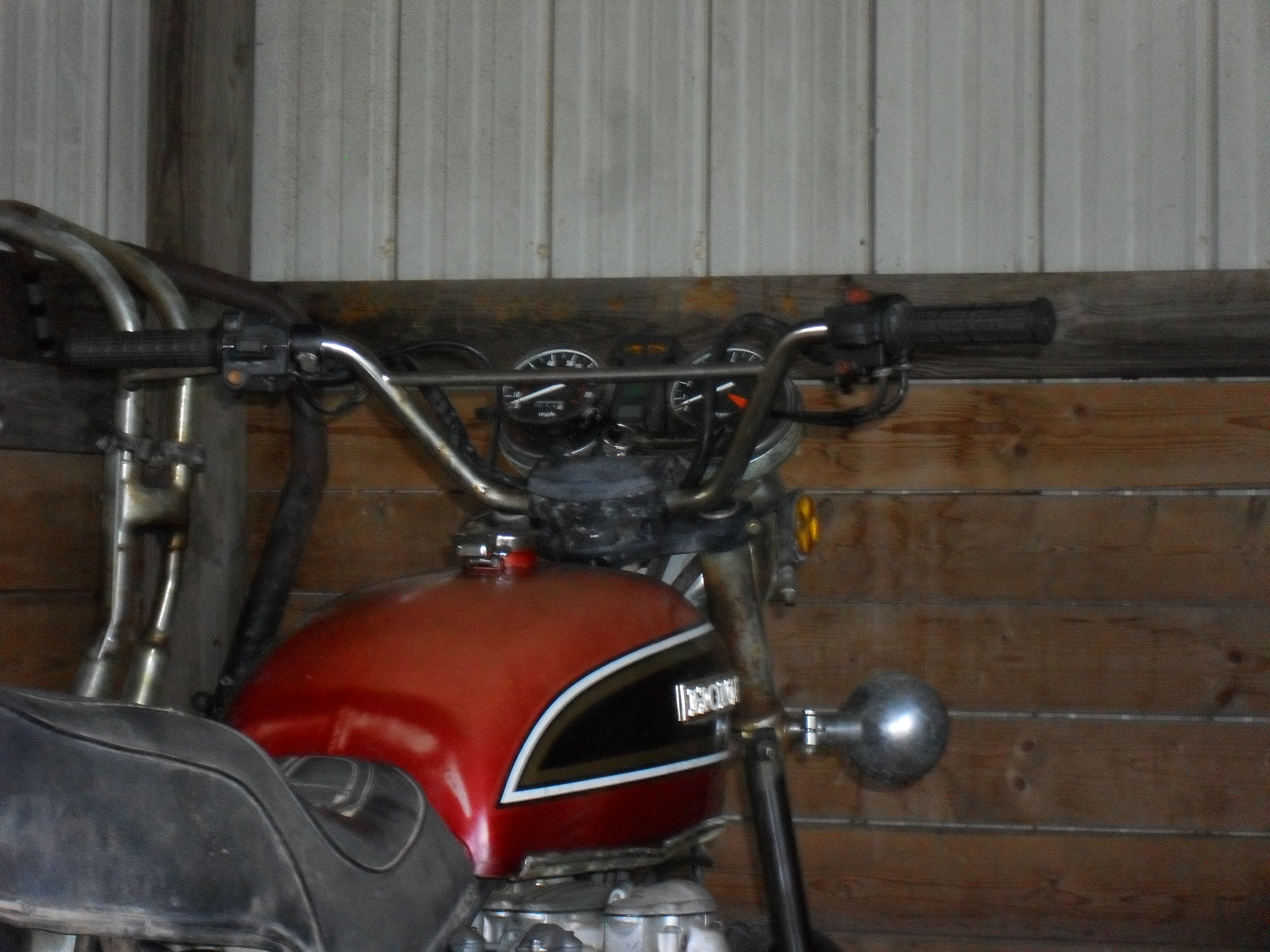
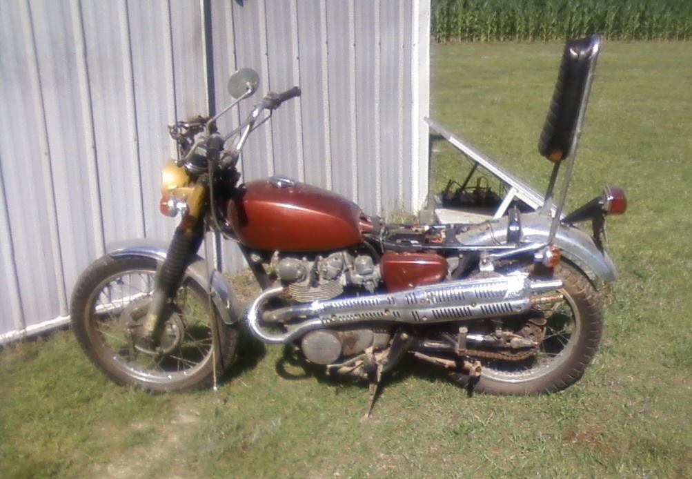
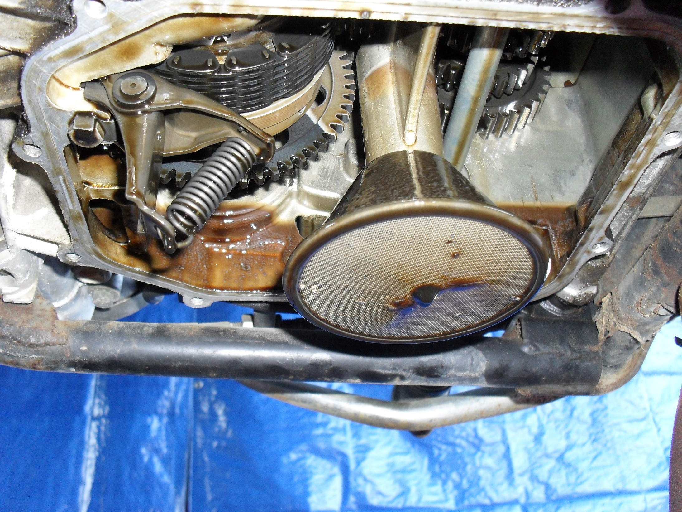
Here I’ve already removed the tank and all of the necessary engine covers.

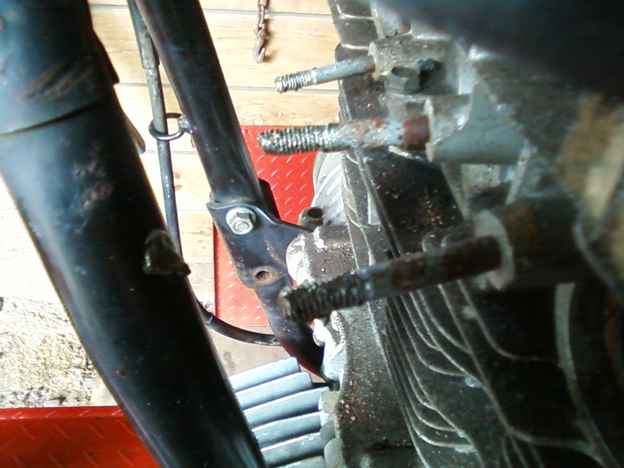
Since I have already put enough miles on this bike since I got it running to warrant an oil change I decided to re-check the valve adjustment for two reasons; one is that as long as the engine had been sitting without running I want to keep a close eye on it for a while & two so that I could show everyone how I do it. As you can see in the photo above I’ve already removed the gas tank, all four spark plugs  and all of the appropriate engine covers. The first thing to do before you adjust the valve lash is to adjust the cam chain tensioner. On a 1980 Honda CB650 this is done by loosening the nut on the rear of the cylinder just a little bit. Do not remove it just loosen it some

Honda CB650 Cam Chain Tensioner Nut

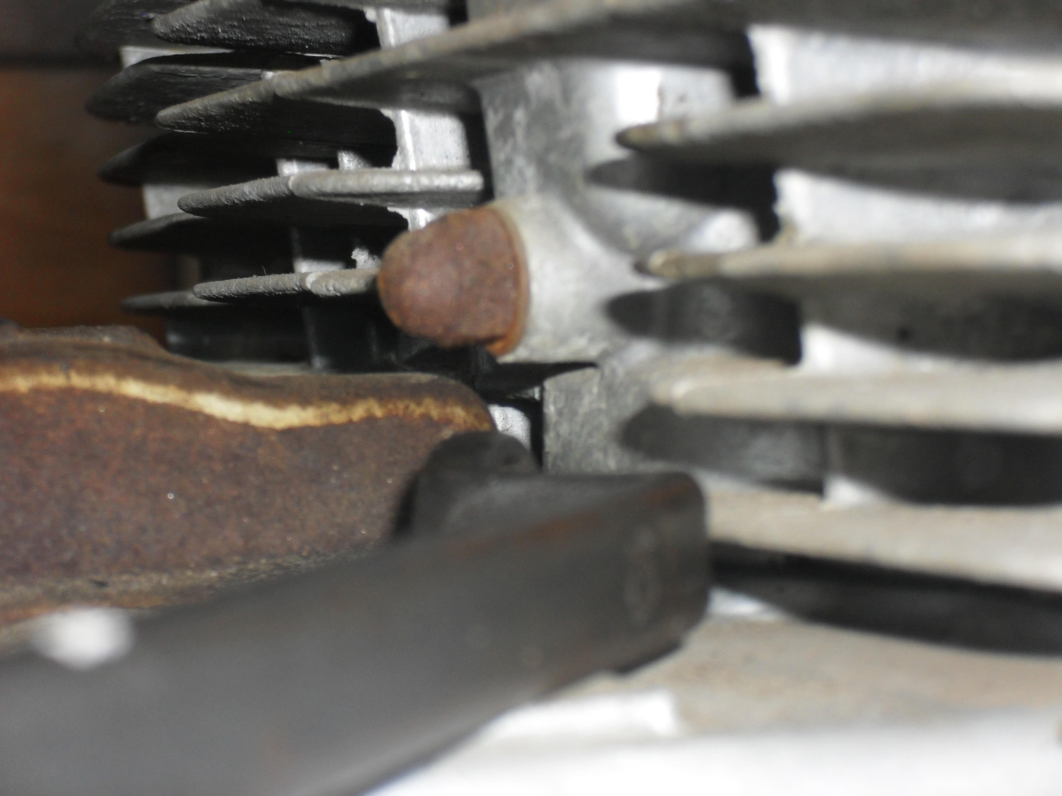
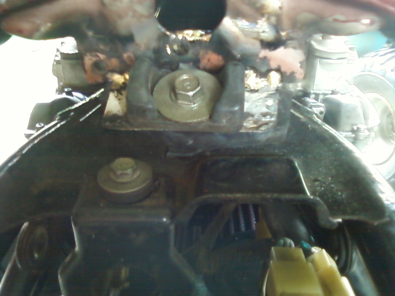
This is the nut you loosen to adjust the cam chain tensioner.

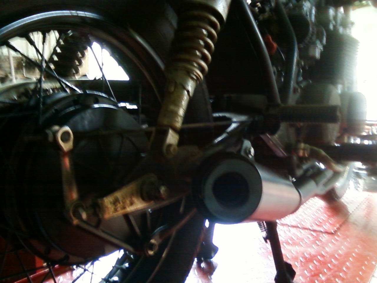
Then put the correct size wrench on the hex spacer behind the nut at the ignition unit on the right side of the engine. Then rotate the wrench clockwise slowly 4 to 5 turns as you simultaneously tighten the lock nut that you loosened at the beginning of this step. This is also the first thing you should try if you own a motorcycle and you can hear the cam chain rattling, but if after making the correct adjustments you still have a rattle then it will be time to start replacing parts. Keep the wrench that you used to turn the crankshaft handy, you are gonna need it a few more times.

1980 Honda Ignition Pulse Generators

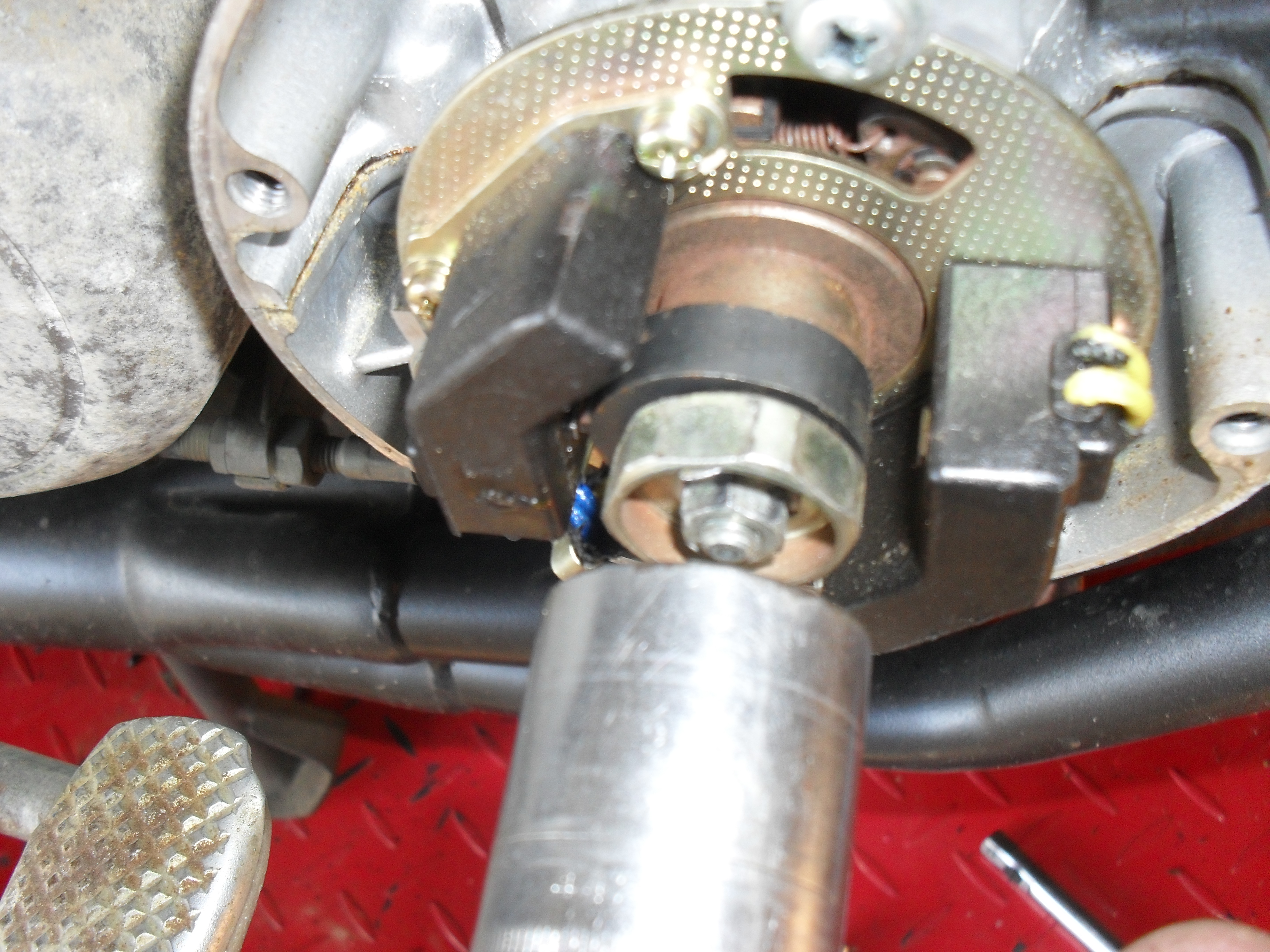
The Clymer manual describes this as a 15/16″ nut. That is wrong this is a 24mm. OOPS

Here in this picture taken on the left side of the engine you can see 2 of the three openings in which we will be working to check & set the valve lash. The adjusters for the intake valves are on the back of the head in front of the carburetors and the exhaust valve adjusters are on the front of the head behind where the exhaust pipes stick out. The first step is to get the number 1 cylinder to top dead center. Take your large wrench and rotate the crankshaft clockwise and watch for the intake rocker arm on the first cylinder to drop down into the head and start to rise back up. Then look at the timing marks on the ignition advance unit (photo is further down the page) and continue to slowly turn the engine until the 1.4 T mark is aligned with the pointer that is cast into the crankcase.

Honda SOHC Cam & Rockers

The camshaft & rocker arms are in the left hole & one of the adjusters is in the right hole.

At this point both the intake & exhaust valve on cylinder number one should be loose enough both rocker arms to be wiggled. If not you either have a valve that is way too tight or you did not stop turning the crankshaft at the right mark, either way you should verify which problem you have before moving on. a simple way to see if the cylinder is at top dead center is to take a long small diameter wooden or plastic dowel and insert it into the spark plug hole. If the piston is at the top of the cylinder the dowel will not go in very far at all.

With the number one piston at TDC on a 1980 CB650 you should be able to adjust both valves on the number one cylinder, The exhaust valve on number two, & the intake valve on number three. Once you have those done you need to repeat the step above but this time watch the intake rocker of cylinder 4 on the right side of the motor cycle. With that one at TDC you can adjust both valves on number four, the exhaust valve on number three, and the intake valve of number two.

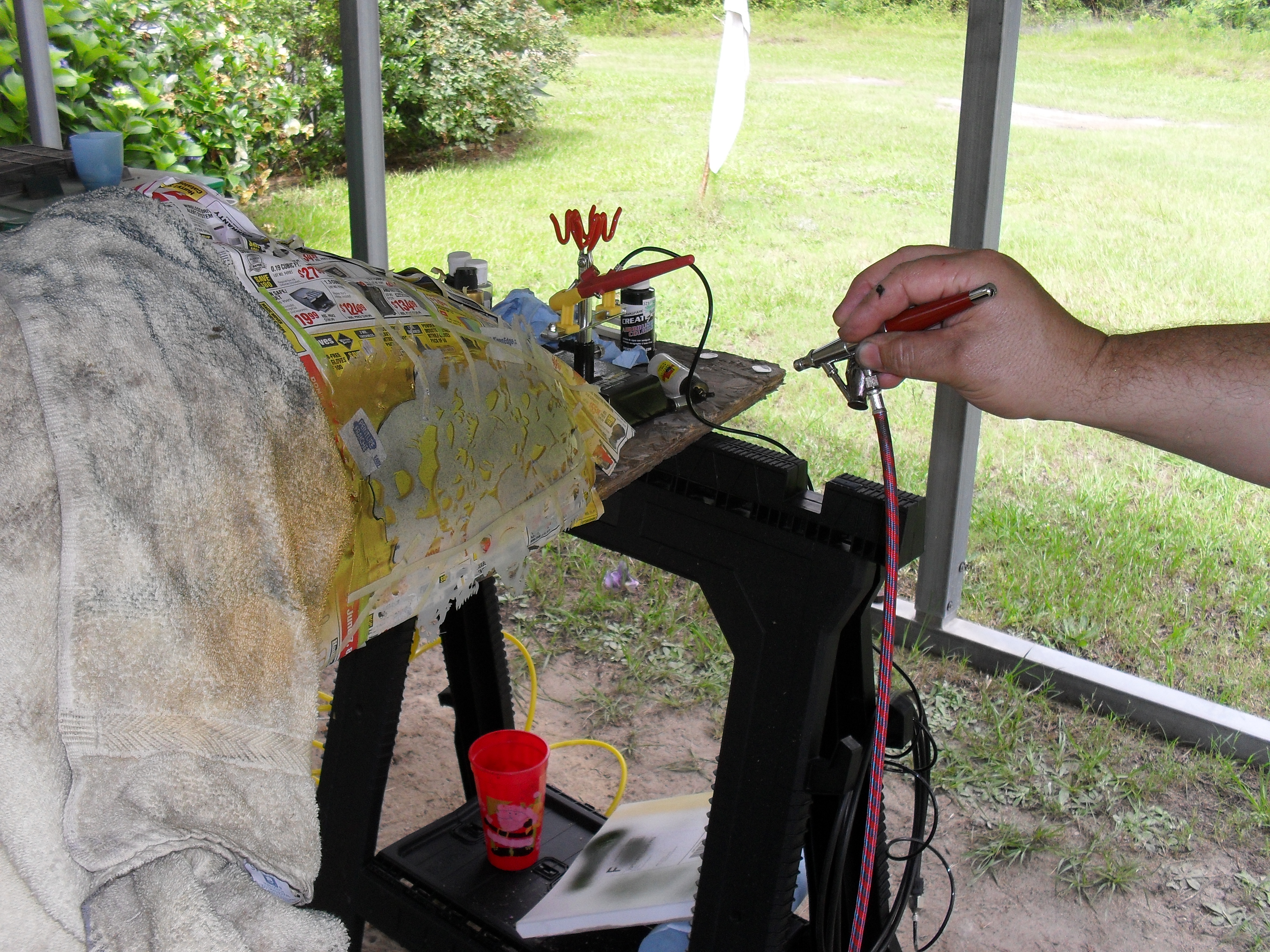
Lets talk about tools for a little bit. All of the shop manuals show a special tool for adjusting the valves, but the simple truth of the matter is that for a number of engines you don’t need them and this CB650 is one such example. For the lock nut, I just clamped a pair of Vise Grips around an old cheap 10mm socket that I have on hand and then just used the proper size of flat-head screwdriver to turn the adjustment screw with. Works great for me on this motorcycle, your mileage may vary, if you break something I’m not responsible, etc.

tools for valve adjustment

Macgyver was an amateur!

Speaking of tools let’s get the feeler gauges to set the valves with. The ones that I use are from Snapon and are about a foot long. The also came with a nifty holder that is very handy for working with the really thinner sizes in hard to reach places. The intake valve lash setting for this generation of Honda CB650 is .05mm (.002 inches) and the exhaust setting is .076mm (.003). So to do this job I will get out three feeler gauges in sizes .002,.003 & .004 (.1mm). Why three sizes? I’ll explain in a minute.

The next picture is of the .002 feeler gauge slipped in between the rocker arm & camshaft. This is where you measure the lash on this engine. Basically what I do is turn the adjustment screw until I can just slip the feeler gauge into place with just a little bit of wiggling. You should tighten the lock nut each time you do this as it may affect the final adjustment. If you tighten the lock nut and find that your lash setting has changed tighten the adjustment screw a bit to compensate, re-tighten the lock nut and check it again. Usually after I do all of this, and I am satisfied with my setting, I then take the next larger feeler gauge (.003) and try to insert it into the gap. If it doesn’t fit great I move on to the next one but if it slips in I readjust the lash until the correct sizes slips in fairly easy but the next size up wont go in. You may wonder why not just set it a little tight and not worry about it? I like to set these things exactly as needed for the best performance. The other reason is the way that motorcycle engine valves wear. Very rarely is there any wear at the top of the valve, most of the wear occurs where the valve closes at the valve seat in the head, this causes the valve lash to get tighter as the engine wears & not looser. This is especially problematic when you are running old motorcycles on the toxic, corrosive, & environmentally unsound corn juice that passes for gasoline in this day & time. If you must err on the side of caution it would be a little tiny bit better for your valve lash to be just a hair too loose than to be to tight.

<setting the 1980 CB650C intake valve lash>

For really thin feeler gauges like this .002 I recommend a holder like this one from Snapon tools.

Next take the .003 feeler gauge & set the exhaust valves as shown here. Then use the .004 gauge to make sure your adjustment is just right. It is especially critical not to over tighten the exhaust valve lash. If the valve wears down and is not able to close all the way due to a lack of clearance you may get a burned valve & a big repair bill.

<adjusting the 1980 CB650 exhaust valve lash>

If you have a late 70s or early 80s Honda with the factory electronic ignition you definitely want to perform this next step. First get yourself a set of nonmagnetic feeler gauges. DO NOT not use steel feeler gauges to set the magnetic pickups aka pulse generators on these bikes.

Brass non-magnetic feeler gauges

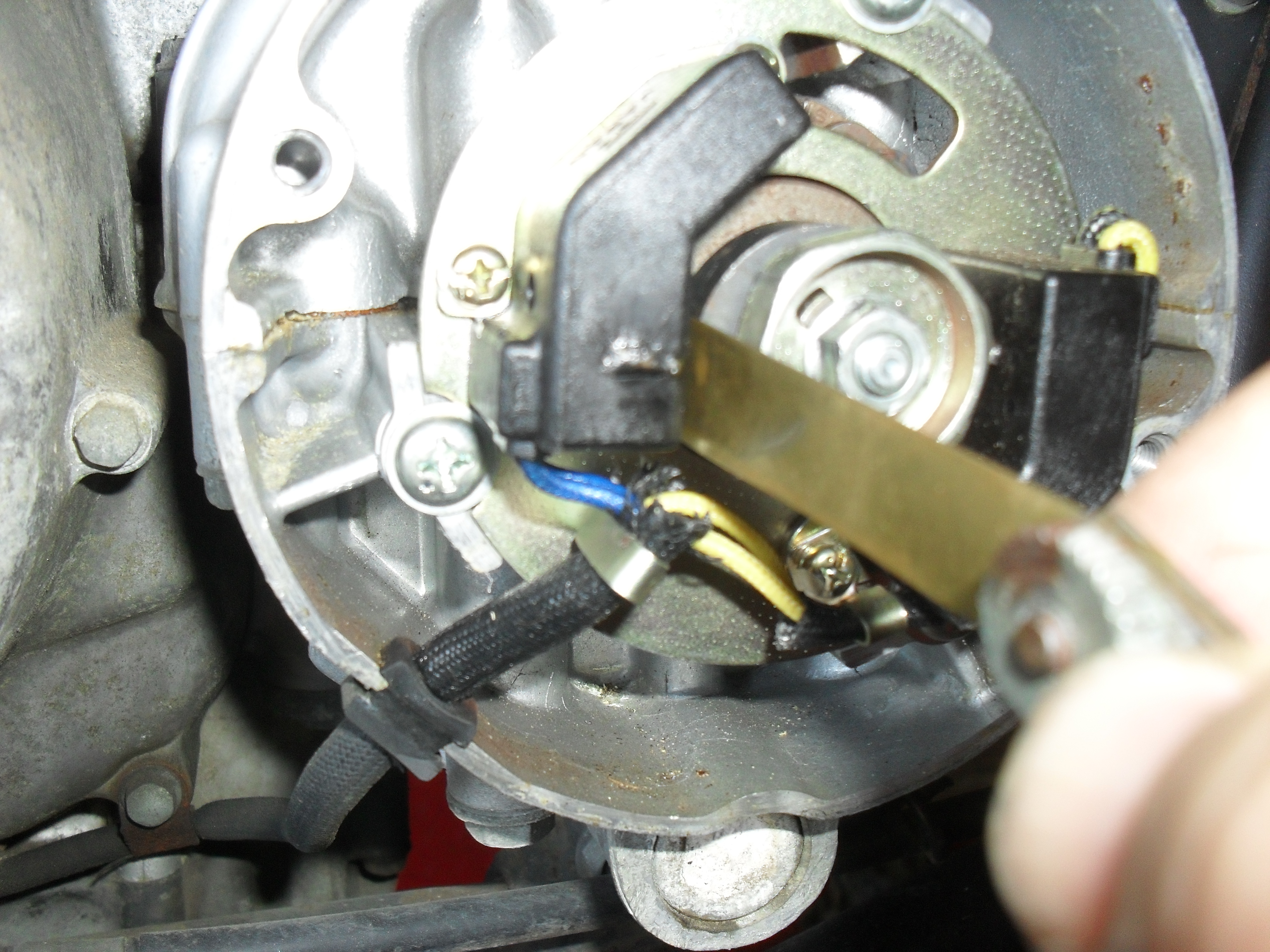
Non-magnetic feeler gauges are a necessity to set air gap on the pulse generator of most OEM electronic ignitions of this time period.

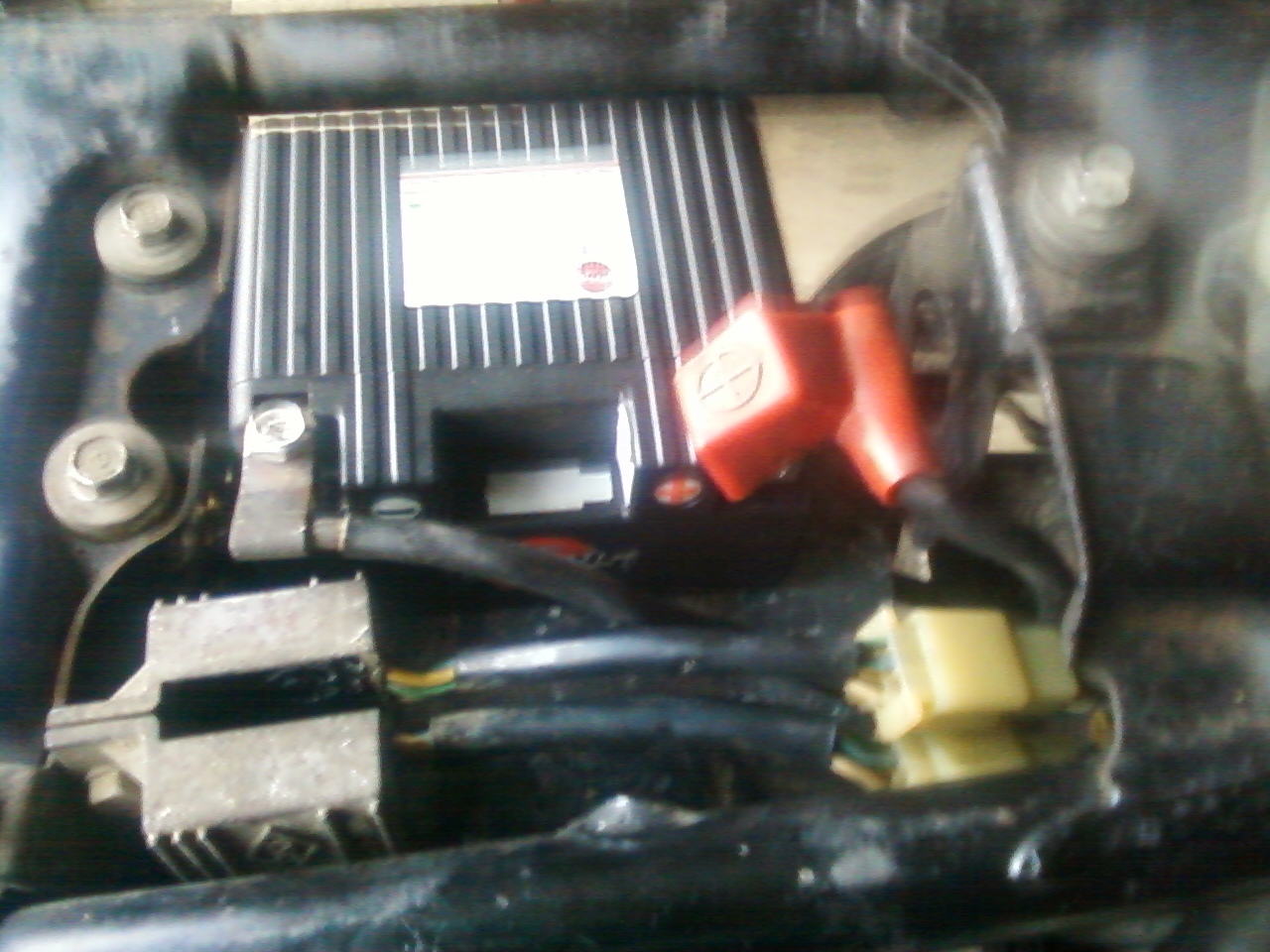
The range of settings for the air gap between the pulse generators (black boxes in the picture below) and the trigger mounted on the end of the crankshaft is .012-.016 inches (0.3-0.4mm) You can also see the pointer & the timing marks that I mentioned above in this picture.

<80 CB650 timing marks, pulsers & advance plate>

1980 CB650 timing marks, pulse generators & advance plate

Believe it or not I have never seen any motorcycles with this gap set correctly from the factory, but the system is still good enough so that most bikes run without any problems whatsoever. Still if you have one of these and it runs okay except for a little surging & hesitation the pulse generator air gap should be the first thing you check. To set mine I just rotate the engine until the trigger ( little square nib sticking out of the crankshaft ) is aligned with nib on the pickup, loosen up the adjustment screws, stick the feeler gauge in place, & hold it all together while tightening the screws back down. Then rotate & repeat to do the other one.

<Honda electronic Pulse generator Air Gap>

This makes a huge difference in engine performance if it is set correctly.

There you have it, put a little lube on the advance mechanism behind the plate, reinstall all of your covers, spark plugs & fuel tank. Now it’s time to fire it up & check it out. Once you are sure that you did everything correctly & your engine is sounding just the way it should take it out for a ride & enjoy the fruits of your labor!

Peace Y’all

The Fool Tank Chronicles : Part Two

One thing that I have discovered while working on this motorcycle is that deliberately building a rat bike is actually a lot harder than it would seem. In all honesty, a deliberately created rat bike should properly be called a neo-rat bike. A real rat bike is a natural creation, a collection of found art held together by grease, road grime & baling wire that accumulates over decades and tens of thousands of miles. People like my self who drag up old bikes & mechanically restore them while leaving the patina semi-intact are actually just posing. But what the heck it’s a lot of fun! Even so the siren song of the polishing machine, paint gun & steel wool are very hard to resist. Have you ever tried to clean just the inside of a dirty weather-beaten old engine cover and then tried to reinstall it so that it looked as if it had never been disturbed? It ain’t as easy as it sounds. Leave the chrome rusty, oh the horrors! Working hard on your sheet metal & then covering with flat or semi-gloss paint instead of making it shine like a brand new penny is very counter intuitive, but sometimes we really enjoy the results.

<drillium on a CB650>

Here’s some of that exotic metal called drillium.

Now let’s get back to my screwing up a perfectly good tank. As I mentioned in part one the original plan was to cut the rear subframe off and install a custom one for that straight framed 60s & 70s look. When that didn’t happen I took my cut down stock seat & had it recovered in black & green & fitted it to the bike & I actually did my shake down runs and a good bit of commuting on it as it was. Still every time I looked down & saw the bottom edge of the tank was nearly a half an inch above the nose of the seat it bugged me. You see even on a rat, craftsmanship counts. It’s one thing if it has dent’s, rust & flaking paint, but if you modify something or deliberately create a faux patina on something you must do it correctly. For example it’s okay to fog some flat black primer directly over a piece of rusty pitted metal but it is totally unacceptable to get a bunch of paint runs while doing so, because that smacks of sloppy craftsmanship. To me, being my own worst critic, that large seat to tank gap was a sign of very sloppy craftsmanship & it had to go. After experimenting with different thicknesses of rubber isolator for the rear mount I was able to reduce the gap down to about a quarter of an inch. Still too sloppy for me so I took a small body hammer & dolly & started rolling the rear seam of the tank down, figuring that I could repair the green portion of the paint by blending. I actually thought it was going to work but when I was almost finished the seam split. I probably could have silver soldered it closed & coated the tank with a sealer, but my boys kept insisting they did not want to chance a gasoline shower at 60 m.p.h. so it was off to ebay to find another tank.

Buying a gas tank for a motorcycle on ebay can be a very scary proposition. When I was rebuilding the Minimum Ninja, I bought three before I got one that was even usable. The sad part is that I had already left the sellers good feed back before discovering the problems. If I were doing a serious show quality restoration I would do my best to source a N.O.S. tank from a vintage parts dealer before buying one at an online auction. Since this was not a restoration I was hunting functional with a few light dings and no rusted out spots. The one I found looked alright, it had a few visible dings, & some rust on the inside but it was good & solid. I went ahead & put in the rear mounts so it would fit a CB650 this time paying very close attention to how it lined up with the front of the seat.

<bondo bucket gas tank>

arrrgh!

<CB750 to CB650C tank adapter>

<spot putty on top of the primer>

Putty smeared all over the tank & I still missed a couple of spots.

Since it was going to be acid washed & lined to keep the rust out of my gasoline, I decided to strip it down & fix the two or three visible dents on the exterior. Then I started removing the paint to fix dents only to find someone had already fixed a bunch of dents. There was already bondo everywhere! Discouraged I actually got back online & began looking for another tank. The problem is that I had already pre-registered for the Bull City Rumble this coming Saturday. So I just stayed up late last Friday night & fixed everything, acid washed it, put in the tank liner & had it ready to paint first thing Saturday morning.

<1970s Honda CB750 tank w black primer>

the black primer was actually kind of cool looking

Since I was doing all this extra work I wanted a nice durable semi-gloss dark green that was in line with my original vision for this bike. Being an old country boy I really like the Majic brand tractor & equipment enamel, it is a catalyzed enamel that although it has a long initial drying period becomes very durable. The downside is of course that you are limited to tractor & implement colors. But that was okay since I never found an off the shelf semi-gloss paint in the color I wanted anyway. instead I poured some John Deere green into a mixing cup & kept adding matte black until I got the shade & sheen that I wanted.

After seeing how it looked I decided not to put the stripes and the airbrushing back on it this time, in fact I even color matched the emblems before re-installing them late Sunday afternoon after giving the paint 24 hours to dry.

<a green Honda gas tank>

As I sit here writing this on Wednesday the Suburban Assault Scrambler is sitting in the carport, yesterday I put gas in it for the first time with the new tank, and rode it to work today. At lunch time I took a bunch of pictures of the finished product sitting in various industrial locations, but you’ll have to wait a couple of more days for those pics. Then I have to rest a little bit & get ready to start on the next project!

<suburban assault scrambler teaser>

The Fool Tank Chronicles Part 1

Some of us just have to do things the hard way, it’s in our blood and it will not be denied. Take me for example, while by no means wealthy in money I could probably buy any new motorcycle I wanted just sign the dotted line & add another automatic draft to my checking account & ride. But even the new retro bikes don’t have the pull on my soul that the old ones do, they aren’t part of my memories, & they don’t need my love to get back on the road. I don’t know about you, but for me the turning of the wrenches, watching dial gauges & degree wheels, the smell of parts washer fluid & the massaging & painting of old sheet metal bring me just as much pleasure a actually riding the finished product. When I finish one project, or sometimes even before I am constantly scanning Craigslist, Ebay, the local trader papers, & the internet message boards to find the next one.

Sometimes I do very irrational things that create far too much work for myself even by my own masochistic, self flagellating standards. This is the story of how I modified & then destroyed a fuel tank for my CB650 Scrambler project, & then had to fix another one.

Let’s start from the beginning, first there was my junk auction CB650C with this very holey tank.

<original CB650C tank>

As you can see there wasn’t much point in trying to fix that one so I used it for target practice & threw it away. Initially my plan was to turn this bike into a shiny polished cafe racer style custom with a big ’70s tank & some clip-ons, so I ordered up a 1974 CB750 tank from Ebay & set it on the bike just to see how it would look. Of course it wouldn’t work with the stock seat so I broke out the sawzall & cut 2 inches from the front of the seat. At this point I was still planning to cut the rear sub-frame off & put in a tail loop to support a proper cafe racer seat with a bum stop, because I had the Ninja for me & Mrs. Psyco to ride around on two up. Here’s a shot of the initial mock up.

<old 750 tank mockup>

old 750 tank mockup

By the time the above picture was taken fate had intervened in two distinctive ways. First we’ve had one of the wettest, nastiest, stormiest, summers on record. The dirt road that I use to get from my hole down in the swamp out to civilization, has been an almost constant quagmire because we have not been without rain long enough for it to dry completely up. This is not an environment conducive to the cafe racer style of motorcycle as your only bike. The second factor was the sale of the Minimum Ninja, I really wasn’t crazy about selling it, but the gentlemen who bought it from me was like a kid going, “please Santa, I’ll take great care of it I promise,” so I finally gave in & let him have it. To his credit he does keep it much cleaner than I ever did. But now I had to get something rolling & fast, preferably something with two up capacity that would roll down a dirt or gravel road just as good as a paved one. Decide to do a flat green rat bike that require minimum cleaning.

I had already made a new rear tank mount at this time by bending the CB750 mount down & brazing in a sheet metal angle the the proper size hole in it.

cb750 to cb650 rear tank mount clamped

cb750 to cb650 rear tank mount clamped

<cb750 to 650 tank brazed>

My ugly brazing

The problem was that at the time I paid no attention the the seat to tank relation, something that would come back to haunt me later. After I changed my mind about the direction of this project but before really fitting everything together I decided to go ahead & change the color, but since I was doing a “rat bike” style build not to fix any dents or chips & just spray can paint it.

<tank number 1 taped up>

tank number 1 taped up

So I taped off the graphics & cap being careful to trim the tape around the nicks and chips hoping that it would look like the new color was original & spray bombed it with what I thought was a flat dark olive color

<tank after painting>

much lighter than I was expecting:(

About this time, I purchased a “skull pile” stencil from Airsick Stencils & decided to play around with it some, so I popped the tank off & taped it up following the instructions on the Airsick website for using these reversed stencils they sell, & sprayed my main color Createx Wicked Gold.

<airbrushing a gas tank>

This color required a lot more thinner than the other Createx colors I’ve used in the past

After spraying the color I then put the stencil back in place and turned my air pressure down a little bit and sprayed in some opaque black to create the details.

airsick airbrush skullies

laying in the skulls

Here’s what it looks like when you take the stencil off.

<an airbrushed skull pile>

Just In case you were wanting to know the airbrush is a Paasche VL & yes I am very happy with it.

<my Paasche VL airbrush>

After finishing up and giving the paint a few minutes to set up I peeled the tape off.

<peeling back the mask>

peeling back the mask

If you try this at home just remember that most commercially available airbrush paints are designed for fabric use & require heat to set them and make them permanent, so go over the surface with a hair dryer or hot air gun & get it good and warm if you don’t want your paint washing off later.

Most people go back over these skull piles & fill in little details with the airbrush & some freehand stencils. Me I cheated a little bit by doing my detail work with a black extra fine point Sharpie, before spraying on the clear coat.

<closeup of airbrushed skulls>

It looked decent enough for a rat bike I thought

<airbrushed tank on cb650 scrambler>

airbrushed tank on cb650 scrambler

It’s kind of a shame that I destroyed this tank while  attempting to correct the big gap between the bottom of the tank & the top of the seat. Oh well if you’re gonna cook an omelet you gotta break a few eggs. I’ll come back in a day or three and tell you the rest of the story.

Vintage Piston Valve Keihin Carburetor Overhaul

Hello again everyone, Lets restore a set of carbs for this old Honda! Yes I had already turned them over one time & popped all of the bowls off and blew them out with some carburetor cleaner and put them back on to test run the old bike & see how it sounded, but it was a running a little lean with the pod air filters, plus I was installing a new exhaust  system and needed to re-jet anyway. But the single best reason I have found to go to this extreme is that there is almost nothing else that will make an old motorcycle run like new again the way a complete carburetor refurbishment will. In fact the only thing better is a new set of carbs, which if you pull your old ones apart & find severe damage or wear to the castings, is your only choice.

Here you see the four carburetors, along with a flathead screwdriver, a JIS screwdriver, a set of mini wrenches and a ratchet with a socket. This is not everything you need to completely disassemble them but it’s a good start. The patient is my own 1980 Honda CB650 Custom with a set of Keihin PD mechanically operated carburetors. Although these a very similar to the piston valve or round slide carbs used on a number vintage motorcycles these do have a few differences from the older ones. This will not be a complete step by step guide to restoring every single piece. If need to learn the basics of carburetor repair I suggest that you start by clicking here.

Instead I will focus on how to disassemble the set of carbs, and point out some of the different features along the way, along with a few tips and tricks to make the job more successful. Please note that successful does not mean easier. This is not rocket science but there are no shortcuts either.

The first step in getting a set of carburetors apart is to remove everything you can from the choke & throttle shafts. Here I am using a JIS screwdriver to remove the choke butterflies. What the heck is a JIS screwdriver you ask? Just click here to find out!

Please note that these screws are often punched from the backside at the factory to spread them out & keep them from coming loose & falling into a running engine. This often makes them a pain in the butt to remove.

Next take the tops off and remove the long screws that connect the slide lifters to the throttle shaft.

Be sure to inspect the shafts for damage like this before you start pulling the unit apart. At some point a previous owner had used a pair of pliers to move a sticky slide. To avoid damage to the bushings etc. use a strip of sand paper or emery cloth to remove anything you find like this prior to dis-assembly.

Once you have everything loosened or removed from the shafts it’s time to remove the brackets that hold the rack together. On this set there is one large bracket on the engine side & two small braces on the air cleaner side.

Then you can slide the two outer carburetors off the shafts and lay them out along with all of the parts that go between each carb. Lay everything out on your workbench in the order that it comes apart with everything facing the direction that it goes back together correctly. It just makes life so much easier. In fact if you have never done this before I suggest taking a copious amount of pictures at each stage of dis-assembly to help you remember if the doohickey is pointed toward the watcha-ma-callit or the thinga-ma-bob.

Here’s a shot of the two middle carbs with the vent hoses in the foreground  and everything else behind them.

On this motorcycle the throttle return spring is fitted between this bracket and the number three carburetor. Carefully drive out this rolled pin to remove the return spring  and remove the shaft completely from all the carbs.

Here is a shot of all the major components laid out on the bench more or less in order. Always keep the parts from each individual carburetor together, never mix them up because there are some small differences in every set even if it just wear patterns. Some machines (but not this one) may even have different jetting between different cylinders so just play it safe and don’t mix your parts.

At this point instead of a big complicated looking rack of carbs, you are now just rebuilding 4 individual carbs with only a few differences from you average

dirt-bike carburetor.

This is one thing that is found on the early emission controlled Hondas (late 70s & early 80s) is this pilot mixture screw with the tab on it to prevent it from being rotated too far in on direction or another. The float bowl must be removed first to remove these screws. Of course if you doing this for an off road, race only machine 😉 you can carefully grind the tab off before re-assembly.

Another big difference on some machines is the presence of an air cut off valve often found under a cover like this. The purpose of this valve is to temporarily restrict the flow of air through idle air circuit when the throttle is suddenly snapped shut. This helps prevent that lean backfire that occurs on some motorcycles when you suddenly let off of the gas.

These valves were later eliminated from some models but the side cover is still there, but it’s just blank. Some folks will actually remove these and solder the holes closed, then re-jet the carbs extra rich to run without them but IMHO that is not the way to go. Yes I know that at 30 to 40 dollars & up each this is a damn expensive little part, but take my word for it if you replace them you will notice difference.

One nasty little surprise is the presence of pressed in pilot / slow / idle jets. pick your terminology but all three words refer to the little brass tube you see in the picture above. If you are restoring a completely stock bike with stock mufflers and airbox then I will recommend you do everything in your power to clean it without removing it. But if you cant get it clean or if you’re like me & think stock sucks don’t fret it can be changed. As far as I know there is only one source for the pressed in jets and that is Sirius Consolidated, one of my favorite purveyors of all things for motorcycle & powersport carburetors. Click here to check them out.

If you’re planning to change them out anyway grab them with a set of pliers, twist a little to break them free & pull them out.

I finally decided to break down and try ultrasonic cleaning. This is a cheapie from Harbor Freight. For my cleaning solution I am using 1 to 1 mixture of Simple Green & water. The only real drawback to this one is that you can only get 1 carburetor in it at the time, and even then the entire carb is not submerged. I just ran every one for the maximum cleaning cycle of 480 seconds and the flipped it over and ran it for the max cycle again. Be sure to put all of the parts for each carburetor in the cleaner, including all of the internal parts, along with the fuel & air vent tubes that run between the carbs.

Being the meticulous and detailed asshole that I am even after the ultrasonic cleaning I blow everything out good with an air gun and rinse well with aerosol carb cleaner. I also use Simple Green in my parts washer & have discovered that if you don’t rinse the parts afterwards they sometimes have soap residue on them. Plus I just like to be sure that all passages are clear.

Here’s a fresh clean carburetor ready to be re-assembled with all new jets. FYI with the K&N pod filters and the Mac Exhaust I am using #42 pilot jets and #120 main jets. and put my initial pilot mixture screw setting at 2 turns out. This set up turned out to work very well with only minor adjustments after starting the engine. I actually arrived at these numbers for my initial set up after perusing hundreds of posts at the HondaCB650.com & the SOHC4.net forums taking notes and basically picking out the jet sizes most commonly reported to be working successfully in these carbs on this bike with pod filters & aftermarket exhaust. Internet research is such a great time saver but remember to put your ego aside & your bullshit detector on high. You’ll have to wade through a river of fiction to get a few drops worth of facts.

Even armed with these numbers I was prepared to pull the whole thing back apart several times to get it right, but I got lucky this time. That does not mean these jet sizes and settings will work for you & your CB650, but they are as good a starting point as any. Back in the pre-internet days I was re-jetting a moderately modified DOHC CB750F and wound up pulling the carbs off and putting them back on a dozen times before I found the perfect combination of performance and street-ability. If you are modifying your motorcycle you should be prepared to do the same.

This was not a cheap process either, I replaced every single piece of rubber & all of the jets in this set of carbs. The cost just for parts set me back over $300 bucks plus shipping. The jets, air cut off valves & the accelerator pump, all came from Sirius Consolidated, everything else is genuine Honda OEM parts, even the o-rings on the crossover pipes.

This is how the air cut off valve diaphragm, spring & o-ring fit into the body.

I preach a lot about service manuals, and yes I usually try to practice what I preach. This allowed me to verify that the float height really was supposed to be 12.6 mm like most of the fine folks on the net were saying. Trust but verify!

Lets talk about that accelerator pump thingy a little bit. It is usually mounted on the #2 carb like this one. It’s purpose is to squirt a little extra fuel into the engine if you suddenly yank the throttle open. Even though it only enriches one cylinder it helps to reduce the lean stumble that results from a sudden inrush of air when you twist the throttle as fast as you can. It’s also great to squirt a little extra fuel into the intake before starting a cold engine if needed.

It  lives under this little cover on the bottom of this carburetor.

Here it is laid out on the bench so you can see how it comes apart.

This shot is just to show you the differences in the #2 float bowl & the rest. These differences are there for the accelerator pump circuit.

At the time of this writing I have found no source for exact replacement parts for the CB650 accelerator pumps. I think this one is for a CL/CB450. The diaphragm is the same but the shaft is longer. so it will have to be cut to match the stock length.

I marked it and then clamped it into a vise with rubber jaws & then filed it to the correct length. Just remember if you get over excited & cut too much off that you have just screwed yourself out of the price of 18 bottles of Guinness Extra Stout.

Modifications are always a pain in the rear. These air filters don’t clear the choke linkage so even more modifications are required. It’s a vicious cycle I tell ya, and not for the faint of heart or the flat of wallet. Modifications beget more modifications & before you know it you have a complete custom motorcycle that will hopefully run at least as well as a stocker. ;0

Just a few more tips for you, re-assembly is pretty much the reverse of dis-assembly. Make sure you wind the throttle return spring up enough to close the slides when released, and always use some form of top quality name brand thread locker on these little screws holding the butterflies in place. If these come loose they can turn your fine running engine into junk if they get into the cylinder.

This picture shows how the spring connects the left & right choke shafts together. Once you have it all back together you should try to “bench Sync” the carbs. Basically you want to get it adjusted so that it appears the all of the slides are lifting at the same time & closing the same distance. A picture of the synchronization adjuster is shown somewhere further down in this post.

Now make sure all of the clamps are on the intake boots loosely, hook up your cables, & then lube the carb spigots & the inside of the rubber boots on the head.

Now push, pull, cuss, twist, shove & pray. If you are reusing the old boots they may be hardened and make this process a little harder. sometimes heating the rubber with a heat gun helps. Just remember that if they are damaged in any way and do not seal properly you must replace them.

Here I am clamping everything down getting ready for the initial start up. I actually started the engine and let it warm up a bit before moving on the vacuum synchronization process.

Once I was satisfied that the engine was basically running okay & that there were no fuel or air leaks I shut off the engine & temporarily installed these adapters in place of the plugs on the engine side of each carburetor. Then each adapter gets a hose between it and this set of gauges.

Before you get started with this procedure it is usually a good idea to have a fan pointed at your engine & running. Sometimes this can take awhile & you don’t want to risk engine damage.

This picture shows the location of the adjuster screw in each carb. Make sure that you always tighten the lock nut securely when you are done adjusting the carbs. The number two carburetor does not have this adjustment on it, it is the baseline and you want to match the other 3 carbs to it. When you get it done all of the needles on all four vacuum gauges should rise & fall at the same time and to the same readings. Now you can put all the tops back on the carbs & begin road testing. Most run just fine, perhaps with a little tweaking of the pilot mixture screws and idle speed if needed. Just make sure that everything else, especially the ignition system is working properly too before road testing the carbs.

Ride as safe as you can & still have fun!

Peace Y’all

How to Deal With Stuck of Frozen Screws & Bolts

I was invited to be a Guest Blogger over at the Clark Heintz Tools blog, so I sat down and wrote for them what I hope is a nice informative article on one of the most vexing problems anyone can have when working on a motorcycle or bicycle. Click here to go check it out.

There is even a picture of the infamous old  Honda oil filter bolt showing just exactly what you might have to do to remove one…..

If you like the post let them know, if you don’t let me know.

Peace Y’all


Mac Four Into One Exhaust for Vintage Motorcycles.

This is the first time I have purchased a Mac exhaust system for one of my motorcycles. In the past I have purchased a few from Kerker, Vance & Hines, Yoshimura etc. Never really gave Mac products much thought as high performance was always the ultimate goal, and I, like so many young men thought they just made cheap replacement systems for oddball old Jap bikes. Fast forward a few years & now my favorite thing to do is customizing oddball old Jap bikes such as this CB650 here. Performance & sound are still important, just not nearly as important as they use to be. Bang for the buck & good availability mean a lot in this day and time & that is two main things that Mac has going for them. Lets get started installing a set shall we? For this ratty old scrambler conversion I picked out a plain black 4 into 1 system with a shorty muffler.

First thing to do is remove the old exhaust and set aside the parts that you may be re-using. One of my favorite things about this system is that it uses the o.e.m. finned exhaust flange that to me, are very important to the looks of an old air cooled engine.

original Honda CB650 exhaust flanges

original Honda CB650 exhaust flanges

I had actually pulled the stock pipes off a couple of weeks ago and just stuffed the ports with rags to keep the critters out.

<cb650 exhaust ports>

the mud daubers around here, love to nest in motorcycle engines

Lets look at what comes with the new Mac exhaust system.

Mac exhaust hardware

Mac exhaust hardware

As you can see in addition to the muffler this set came with new split collars, muffler clamp & bolts, and 2 different hanger bracket. not shown in this picture is the new center stand stop that comes with it.

The split collars were joined together by a small strip of metal that was left when they were sawed in two. Resist the urge to break them apart.

new Mac split collars

new Mac split collar

After you place the o.e.m. exhaust flanges on your new head pipes carefully spread the collars open just barely enough to go over the pipes and then squeeze them back together so that you only have one piece to hold in place while you position the flanges & start the nuts.

split collars on Honda exhaust

split collars on Honda exhaust

I always use plenty of anti-seize compound on exhaust studs and so should you.

anti-seize compound on exhaust studs

Have some mercy on the next person to remove he exhaust system on your scoots …

Here’s a shot of the pipes in place, I had to pull on the pipes a little to persuade them into place, nothing major just a little tugging & spreading. After you get the pipes in the ports and the flanges back on do not tighten the bolts all the way down until you get the entire system installed.

<Mac Performance Motorcycle Exhaust>

Mac shorty muffler

Mac shorty muffler

Put the clamp on the muffler and slide it into place and then get your hanger bracket and figure out which one you need to attach the muffler to the passenger foot peg bracket.

exhaust hanger brackets

exhaust hanger brackets

The enclosed instructions said to use the short bracket for a CB650C (custom cruiser model) which is what this bike started off as, but in my case it did not fit. I don’t know why and it really does not matter that much to me. The longer bracket worked just fine, I bent the dog leg into it so that it would support the muffler at its natural resting point on the head pipe instead of pulling it in toward the bike. Now tighten all of the bolts attaching your new exhaust to the motorcycle to the correct final torque.

The process of tightening the clamp & muffler mount does bring me to my one major pet peeve with darn near every major motorcycle accessory manufacturer doing business in America. Here I am working my way through this install with the 3 wrenches that will disassemble 90% percent of motorcycles existing in the world today a 10mm, a 12mm & a 14mm, and I have to stop what I am doing and go get a 1/2″ wrench to install the last 2 bolts. I realize that when some of these products were first created back in the ’70s & early ’80s metric hardware was a little more “exotic” and not as cheap and easy to find as the “standard” stuff, but here in 2013 there is no excuse whatsoever to still have standard fasteners on accessories for European & Japanese motorcycles or for that matter modern Harleys & Triumphs too. It would only take a little effort & I for one will be eternally grateful.

On the other side of the bike install the new center stand stop, unless of course you are planning to remove the stand.

<center-stand stop>

After I got it all on, it looks the part & sounds great too.

Mac 4 into 1 On Honda CB650

Mac 4 into 1 On Honda CB650

With this system I get to retain the center stand, have easy access to the oil filter & I have a little cash leftover too!

Did I mention that it has a mean sounding growl too! Click this link to have a listen.

Peace Y’all

9-1-113  Just a quick update on one minor problem that surfaced after 3-400 miles of road time. The rivet holding the baffle in became loose, allowing the baffle to rattle inside of the muffler until it got hot and expanded. My solution was to tack weld the baffle into place & repaint, but one could just drill out the rivet & replace it with a bolt & nut, if by some chance you have the same problem too.

Use the Right Tool for the Job! A Tech Tip & Product Review Combined!

It is time for me to make a confession of my own ignorance. For over two decades I have not been using the correct screwdrivers to work on my beloved old rice grinders. Even during the time I worked as a dealership mechanic I destroyed countless fasteners by using the wrong screwdrivers. I did find by experience, that the really high quality & expensive Snap On brand could usually remove those annoying cheesy easy to strip cheap ass Japanese Phillips screws. But even then the heads still looked mangled for some reason.  Day after day I cursed the engineers at Honda, Kawasaki, Yamaha & Suzuki for sourcing such horrible fasteners to hold such fine machinery together.

Fast forward a couple of dozen years and one day while wandering through a motorcycle show, I stop at a VJMC display and pick up a copy of their magazine.  When I finally slowed down enough to read through it a couple of weeks later I saw a really great article on the difference between Japanese Industrial Standard screws & Phillips screws as used here. It was a real eye opener, no wonder these screws were so difficult to remove. The angles of the sides and the shape of the center are just different enough to cause these two different styles not to be interchangeable.

I jumped onto the internet to research these JIS screwdrivers & found the two most commonly available brands to be Vessel & Hozan. I decided to order a 4 piece set of Hozan screwdrivers for about $25 USD.

Hozan JIS screwdrivers

Hozan JIS screwdrivers

These screwdrivers have hard plastic handles, this bugs some people but most of my screwdrivers have hard handles it  is what I’m used to. Plus they are a lot easier to clean than cushion grips. The distinctive shape keeps me from confusing them with my regular Phillips head screwdrivers which is important. They will probably bugger up a Phillips screw the same way a Phillips screwdriver buggers a JIS screw.

Even though I’ve only used them a few times I am really impressed with how much better they fit & grip the screw heads on a few dirtbikes that I am working on. And the best part of all is that the screws still look good when I am done. This is very important if you are doing restorations or building show bikes.

Save yourself a lot of trouble, learn from my mistakes and get yourself a set JIS screwdrivers. You’ll be glad you did!

A Custom Battery Tray & Other Stuff

Just thought I’d do a quick update on some of the things that I have done with my CB650 project. I have been working on it a little at the time between my normal day job, a few bikes & atv’s for other people, & some painting (airbrush practice & landscape oil painting). Since I’ve decided to go with the “rat suburban assault scrambler” look some of the things about this project have gotten easier, but other design ideas require just a little more ingenuity. Rather than sawing off the back half of the frame & welding in a new seat loop as required to get the proper cafe racer look I am opting for a modified stock seat with a 74 CB750 tank, but I still wanted to eliminate the stock side panels. My plan now is to replace the side covers with 2 pieces cut from some rusty old expanded metal sheet I have lying around. To do that I still needed to modify the mounts for the electrics, and since I will be using a Shorai lithium battery that is much smaller than stock, a custom battery tray was in order also. Since this is a rat I decided to do this with nothing but materials I already had on hand. After sitting down & staring at it a while with my note book, pencil & ruler in my hand I came up with a basic design that tucks everything up high, bolts into the stock mounts, & allows me to reuse the inner fender to protect the electronics. Here’s how it goes…

First I removed the stock battery tray, along with the airbox & some other now useless items. Then I drilled out all of the spot welds holding the mounts, & various brackets to it.

butchering a Honda CB650 battery box

butchering a Honda CB650 battery box

In the spirit of my deep back country roots I decided to make do with the stuff I had on hand & not buy any new stuff to make this from, so this left over shelf divider that was destined for the scrap bin will get to live on as a motorcycle part. Here it is with all of the brackets & mounts salvaged from the original battery box.

custom built motorcycle parts

a custom battery & electronics tray in kit form 😉

Then using my band saw I cut the tray to shape & bent it in a vise.

<custom motorcycle battery tray blank>

Then I bolted the stock mounts back into place using the original hardware & clamped the tray in between them. Since I do not have a tig box for my welder (YET) I simply use a 1/16″ 6013 rod to tack the pieces together without burning through the sheet metal too much.

tack welding battery box

tack welding battery box

After I got it tacked together with the stick welder I took it out and flipped it over & then brazed it securely together with the oxy-acetelyne torch. Then I laid out the various components such as the rectifier, turn signal flasher & etc & then brazed those mounts to the bottom of the plate.

custom rat motorcycle electronics mount

custom rat motorcycle electronics mount

I know it looks awful, but I might just leave it that way, this is a rat after all. I will have to sort & secure all the wiring though, because neatly sorted wiring is easier to trouble shoot in the future & is less likely to develop problems that need trouble shooting.

Here’s a view from the top side showing the Shorai battery lying on it’s side. I still need to make a plastic box to keep the battery from sliding around. Since my day job is doing design work using Solidworks, I may just draw one up & have it printed out using a 3d printer. If not I’ll form one out of ABS sheet.

<Honda CB650 battery box Shorai LFX>

fits just right!

I can’t say enough good things about these batteries, they’re light, powerful & durable. I’ve installed them in a couple of customer bikes, this one, and even have one in my lawn mower! Sure the cost a little more than the lead acid batteries, but are in my opinion a threefold improvement in all areas. I do sell these & would be happy to quote you one if you contact me.

Here a couple of other items that have been added, first an Ebay find of a 74 Honda CB750 fuel tank. This fit with modified rubbers & a custom rear mount. I’ll show you some more details later after I have it all worked out with the seat fitment. but I think it looks really good on here!

Honda CB650 with CB750 tank

Honda CB650 with CB750 tank

Another Ebay purchase is this 1970 Honda CL450 Scrambler. I bought the whole bike just to get the handlebars!

1970 Honda CL450

1970 Honda CL450

It’s pretty much seized up and there’s no paper work but the handlebars gave me exactly the look I wanted for my project. Good solid bars with just enough crust to blend in. No need to treat a new set of bars to a faux patina.

1970 CL450 handlebar on 80 CB650

1970 CL450 handlebar on 80 CB650

The CL450 will be parted, I plan to keep the frame, engine, carbs, gauges, charging system, fork & wheels. All of the sheetmetal and the exhaust are up for grabs to my fellow hobbyists who want them. The fuel tank is rusty bondoed junk but everything else is decent. Contact me using the form below.

I had a few other adventures including dealing with a stuck oil filter bolt that I’ll go over with you soon including how far I had to go to get it out.

Peace Y’all

← Back

Thank you for your response. ✨

Oil Sump & Strainer Cleaning

Alright! You’ve got your latest barn/field/junkyard find home, it still had good compression, so after cleaning the carbs, topping off the oil and putting in fresh gas it actually fired up and ran okay. Yeehaa! now comes the hard part, do not immediately go running in the house to scour the internet looking for the thousands of dollars worth of parts & accessories you need to restore or customize your new to you machine, there is one more thing you must do to be sure that you don’t need to tear the engine down to bare cases, or perhaps just throw the whole damn thing in the trash. Most vintage Japanese & British machines have an oil sump (oil pan to some of you) strainer, that has probably never even been looked at since the machine left the factory. For this lesson we are going to remove the oil sump (pan) from my personal 1980 Honda CB650 and see what we find inside. After a few minutes running time  & a valve adjustment this old thing has less the 8 p.s.i. difference in compression from the lowest to highest cylinder, I can live with that, if there is nothing wrong in the bottom end. Lets have a look shall we.  First if you have a lift put it up on the lift securely.

1980 Honda CB50 on Harbor Freight Motorcycle lift

Let the serious work begin!

The mufflers are off of mine because I am planning on binning them anyway, it is not necessary to remove them for this job on this motorcycle.  On some bikes it may be required, refer to your service manual for details.

Locate the oil drain plug,

Honda CB650 oil sump drain plug

the location of the drain plug & oil pan bolts

and remove it with the appropriate wrench and drain the oil into a catch pan.

Honda CB650 Drain Plug Location

be sure to catch the aluminum sealing washer.

Since this involves changing the oil you might as well go ahead & change the filter too. On these old air cooled Hondas the filter is a cartridge in this housing on the front of the engine.

Honda SOHC Four oil filter housing

Oh no! this bolt has pliers marks on it. Not cool.

Remove the filter and housing, be sure to move the catch pan so that it catches the oil from the housing.

removing the oil filter bolt

removing the oil filter bolt

Now move to the bottom of the machine and begin loosening the bolts on the sump. The CB650 has 10 bolts that are all the same size & length, so all I have to do is don’t lose any. If you motorcycle has different size or length bolts holding the sump on be sure to note which bolts go into which holes.

the motopsyco hard at work

the motopsyco hard at work

Before you completely remove the last bolt and thus the sump be sure you slide the drain pan back into place beneath the engine.

Before you rush to dump the oil pan set it on the bench and have a good look at the goo stuck in the bottom of it. This will tell you a lot about the health of your engine. Believe it or not the crappy looking mess in the picture below is actually what you hope to find.

inside the CB650 oil pan

inside the CB650 oil pan

This one has a thick coat of clutch dust & what ever dirt that got into the engine & settled out of the oil, what I don’t see are any pieces of gear teeth or metal shavings that indicate an serious problem with the engine or transmission. Now take a magnet & swish it around in the muck to see if it picks up anything. Mine came back clean this time. This is no 100% guarantee that all is well with the transmission etc. but it does make me feel better about buying the parts needed to get it ride-able.

<cb 650 oil sump craftsman magnet tool>

Now it is time to inspect & clean the strainer screen.

location of oil strainer Honda CB650

location of oil strainer Honda CB650

While you are down ther3 have a peek up into the engine to see how everything looks.

<inside the bottom of a Honda engine>

this all looks good in here

On a CB650 slide the drain pan back under the engine & pull down on the strainer, it should slide out.

remove CB650 sump strainer

just pull it straight down.

Once you get it out carefully inspect the screen and if it is damaged or loose replace it. If it looks good wash it out in the parts washer.

1980 CB650 oi sump screen

Inspect the strainer & its o-rings if you have any doubt about their condition, replace them.

Now you just have to clean everything up inspect & replace all gaskets & o-rings as needed, and reassemble everything in reverse order installing a new oil filter & fresh oil. NOw you know that you have one less thing to worry about.

Peace ‘Yall

Something to Write With (& other essential documentation tools.)

For this random tech tip I am going to talk about one of the best tools that you absolutely must have in your toolbox, a notepad & something to write with. Some mechanics and owners even go so far as to keep actual log books of the work they do. These are wonderful people to do business with & buy motorcycles from, and if it suits your personality I highly recommend that you do the same. For the rest of us, myself included, who are not quite so anal, a small note pad or note book is essential to write down the occasional part number or measurement.

the ever useful notebook

the ever useful notebook

I have even sketched out an assembly or written down re-assembly directions for things that I have taken apart. Even if you have an eidetic memory, sooner or later you will likely miss some small detail or another, but the act of writing things down helps you to remember them better, and prevent mistakes in re-assembly, parts ordering & custom fabrication.

A good cheap calculator is another great item to have for doing quick calculations & conversions. If you are a machinist or a designer you will probably have a scientific calculator but for the vast majority of us, a simple little calculator is all you need for things like figuring out what size shim to use when adjusting valves, or how much further a part can go before it hits the wear limit. Here I must confess to overkill, since my day job is working in the engineering department of a local industrial equipment manufacturing company I own multiple  scientific calculators, it’s just how I roll.

And last but not least you probably have one of the greatest, & most handy mechanical tools right there in your pocket. A smartphone with a camera has become one of my favorite ways of documenting progress on a job or a project. Take a picture before you start, take another one for each part you remove. Then if you need to refer back to your pictures to remember which way the thinga-ma-bob fits into the doohickey, you have pictures to refer back too.

By the way, here is a quick update on my Honda CB650 project bike. Originally purchased to be modified in the “cafe racer” style I have since changed my mind and am now currently pursuing an “urban scrambler” style. This is going to be really cool so stay tuned!

1980 Honda CB650

Got the airbox & other non- essential stuff out of the way!