
Today I’m going to show you how to perform a Honda CM400 valve adjustment. This basic procedure covers 1978-81 CM & CB400T Honda twins. This engine is from a 1980 CM400. Please refer to a proper CB/CM400 service manual to verify the exact procedures & specifications for your motorcycle. I will give the valve lash & misc. other tune up specs at the bottom of the page.

Gather up the tools you will need along with a copy of the appropriate service manual. Please note that it is not necessary to remove the engine from the motorcycle to perform this procedure, I already have this engine out so that I could do some some fabrication work & painting to the frame. This is the long delayed Project wAmmo bobber that I should have finished months ago, but now I am back on it with a vengeance. You will need to remove the fuel tank, gear shifter, and whatever other parts are necessary so that you can remove the valve cover & the left side crankcase cover. Once all of that is done then remove both sparkplugs.
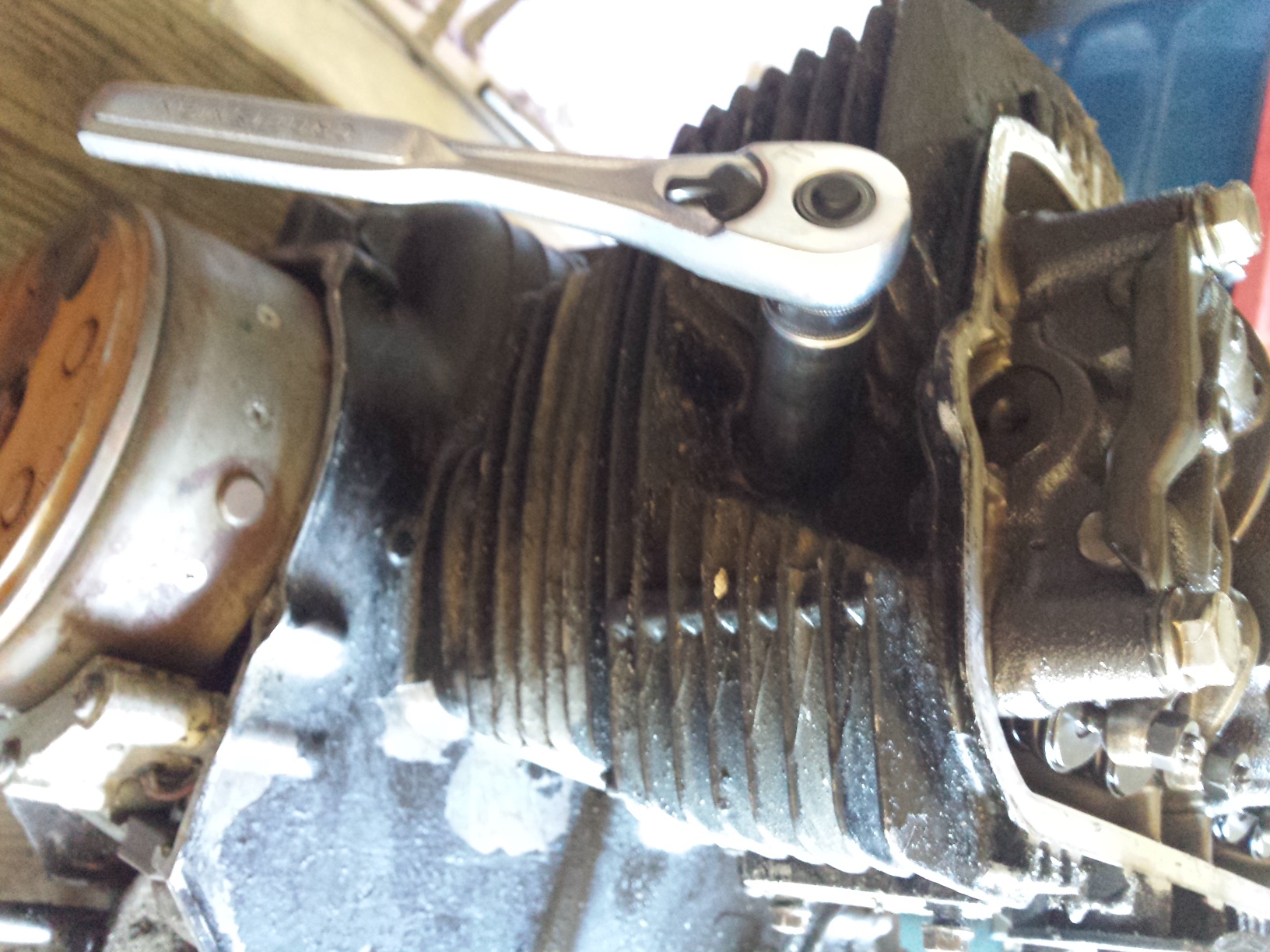
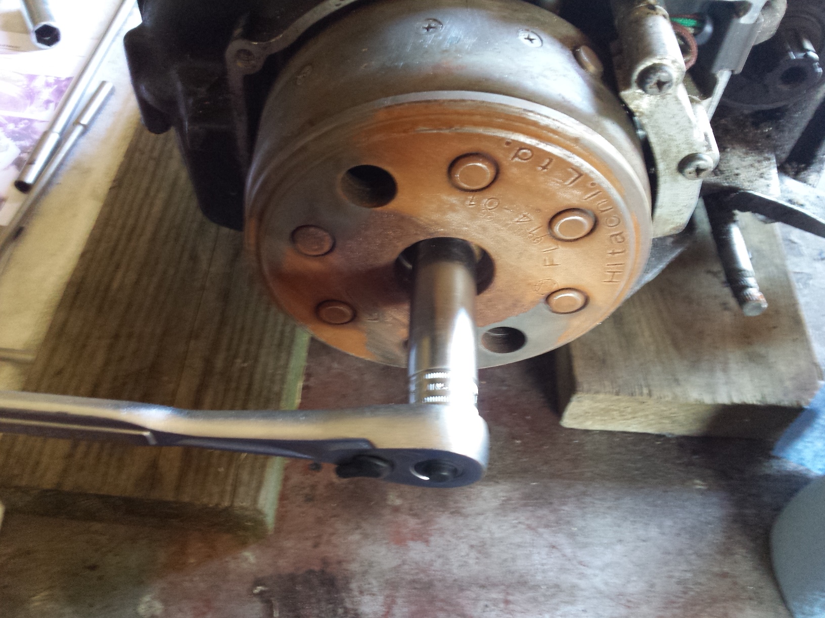
After you remove the spark plugs, switch sockets & turn the engine in the direction indicated by the arrow on the alternator rotor. The big rusty flywheel looking thingy you see in these pictures for those of you who have never seen one before. This one had to have some of the rust sanded off so that I could see the markings on it.
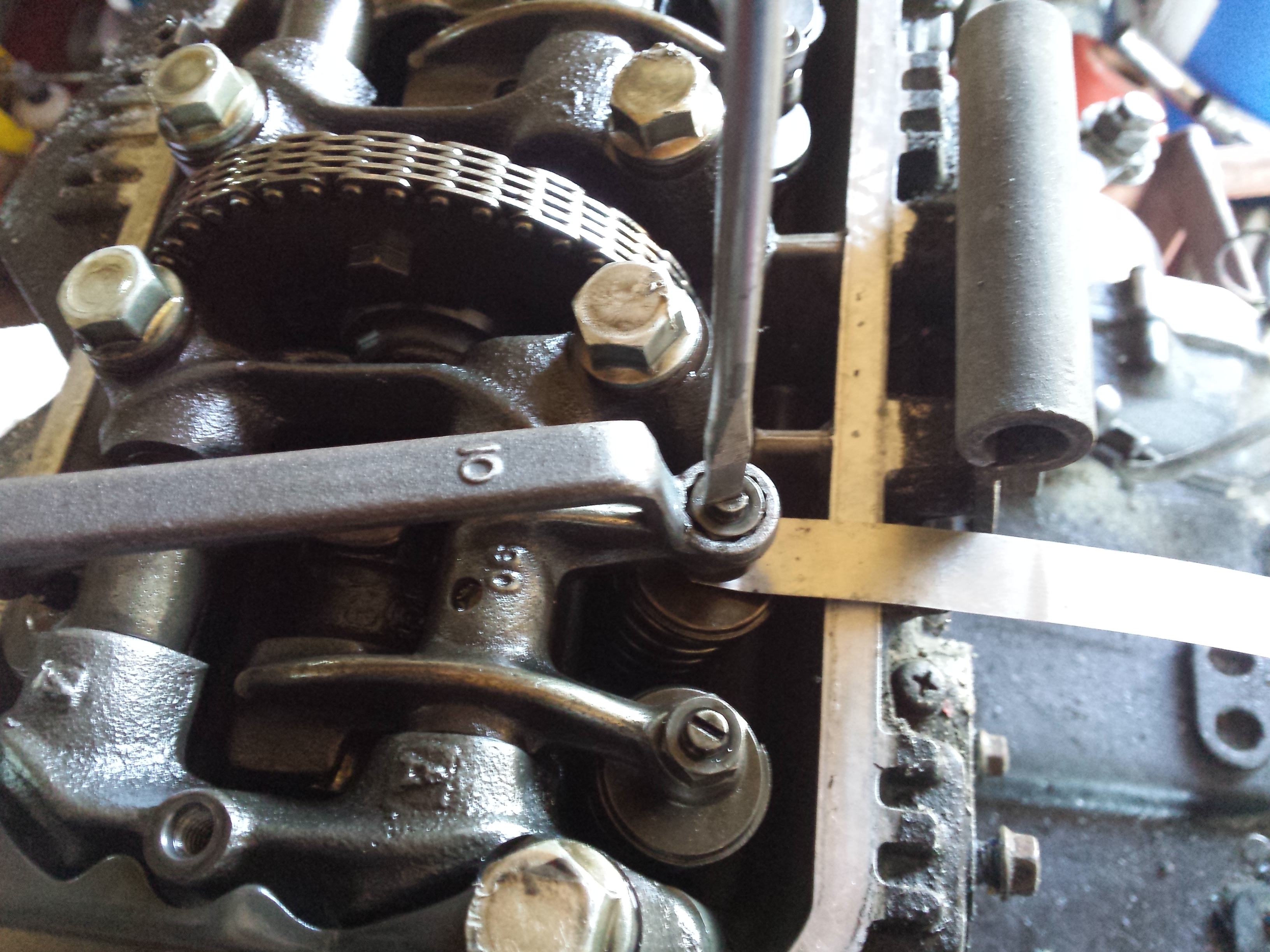
Turn the engine and watch for the intake valve rocker arm on the side you are adjusting to move down and then back up. These little Honda twins have a 3 valve per cylinder layout with 2 intake valves & 1 exhaust valve per cylinder.

Once the intake rocker arm returns to the top continue to turn the engine slowly and line up the next “T” mark on the flywheel with the pointer on the engine case, as it comes around. If the exhaust rocker arm starts to move you have gone to far & must circle the engine all the way back around & start over. Do not turn the engine backwards to get to the timing mark if you miss it.

Then verify that the piston is indeed at top dead center. On this engine it is fairly easy to do just by looking into the spark plug hole.
With the piston at top dead center for the cylinder you are adjusting both the intake & exhaust valves should a little bit of play in them unless the engine has severe wear or improper maintenance that has caused valve recession which will close up the gap. Too much lash is also detrimental to your engines performance and will cause your engine to tap very loudly. Too little lash will eventually lead to a burned valve if it doesn’t close completely.
Loosen up the lock nut for whichever adjuster you choose to start with, here I am starting on the exhaust side.

Then insert the proper size feeler gauge, loosening the adjuster with a flat screwdriver if needed.

Then carefully tighten the adjuster screw & lock nut until the feeler gauge is able to be removed & re-inserted with just a little bit of drag, but the next size larger feeler gauge should not fit. It will be necessary to hold the adjuster screw with the screwdriver as shown below while you are tightening the lock nut. Be sure to recheck your lash after you tighten down the lock nut for good, sometimes you may have to readjust to compensate for the adjustment screw moving when you torque the lock nuts.
Once you have all of the valves adjusted properly replace the engine covers being sure to inspect & replace all gaskets & seals as needed.
Valve lash and some miscellaneous tune up specs are below:
Intake valve clearance 0.10mm +/- 0.02mm 0.004″ +/- 0.0008″
Exhaust valve clearance 0.14mm +/- 0.02mm 0.006″ +/- 0.0008″
Idle speed 1200 rpm +/- 100 rpm
Spark plug NGK-D8EA or ND-X24ES-U
Spark plug gap 0.6~0.7mm 0.024~0.028″
Oil capacity 3 liters 3.2 U.S. qt.s
Hopefully this has helped someone out.
Happy Wrenching!


